
Virtualization
OpenShift Virtualization installation and usage.
Abstract
Chapter 1. About
1.1. About OpenShift Virtualization
Learn about OpenShift Virtualization’s capabilities and support scope.
1.1.1. What you can do with OpenShift Virtualization
OpenShift Virtualization is an add-on to Red Hat OpenShift Service on AWS that allows you to run and manage virtual machine workloads alongside container workloads.
OpenShift Virtualization adds new objects into your Red Hat OpenShift Service on AWS cluster by using Kubernetes custom resources to enable virtualization tasks. These tasks include:
- Creating and managing Linux and Windows virtual machines (VMs)
- Running pod and VM workloads alongside each other in a cluster
- Connecting to virtual machines through a variety of consoles and CLI tools
- Importing and cloning existing virtual machines
- Managing network interface controllers and storage disks attached to virtual machines
- Live migrating virtual machines between nodes
An enhanced web console provides a graphical portal to manage these virtualized resources alongside the Red Hat OpenShift Service on AWS cluster containers and infrastructure.
You can use OpenShift Virtualization with OVN-Kubernetes or OpenShift SDN.
You can check your OpenShift Virtualization cluster for compliance issues by installing the Compliance Operator and running a scan with the ocp4-moderate and ocp4-moderate-node profiles. The Compliance Operator uses OpenSCAP, a NIST-certified tool, to scan and enforce security policies.
1.1.1.1. OpenShift Virtualization supported cluster version
OpenShift Virtualization 4.15 is supported for use on Red Hat OpenShift Service on AWS 4 clusters. To use the latest z-stream release of OpenShift Virtualization, you must first upgrade to the latest version of Red Hat OpenShift Service on AWS.
1.1.2. About volume and access modes for virtual machine disks
If you use the storage API with known storage providers, the volume and access modes are selected automatically. However, if you use a storage class that does not have a storage profile, you must configure the volume and access mode.
For best results, use the ReadWriteMany (RWX) access mode and the Block volume mode. This is important for the following reasons:
-
ReadWriteMany(RWX) access mode is required for live migration. -
The
Blockvolume mode performs significantly better than theFilesystemvolume mode. This is because theFilesystemvolume mode uses more storage layers, including a file system layer and a disk image file. These layers are not necessary for VM disk storage.
You cannot live migrate virtual machines with the following configurations:
-
Storage volume with
ReadWriteOnce(RWO) access mode - Passthrough features such as GPUs
Do not set the evictionStrategy field to LiveMigrate for these virtual machines.
1.1.3. Additional resources
1.2. Security policies
Learn about OpenShift Virtualization security and authorization.
Key points
-
OpenShift Virtualization adheres to the
restrictedKubernetes pod security standards profile, which aims to enforce the current best practices for pod security. - Virtual machine (VM) workloads run as unprivileged pods.
-
Security context constraints (SCCs) are defined for the
kubevirt-controllerservice account. - TLS certificates for OpenShift Virtualization components are renewed and rotated automatically.
1.2.1. About workload security
By default, virtual machine (VM) workloads do not run with root privileges in OpenShift Virtualization, and there are no supported OpenShift Virtualization features that require root privileges.
For each VM, a virt-launcher pod runs an instance of libvirt in session mode to manage the VM process. In session mode, the libvirt daemon runs as a non-root user account and only permits connections from clients that are running under the same user identifier (UID). Therefore, VMs run as unprivileged pods, adhering to the security principle of least privilege.
1.2.2. TLS certificates
TLS certificates for OpenShift Virtualization components are renewed and rotated automatically. You are not required to refresh them manually.
Automatic renewal schedules
TLS certificates are automatically deleted and replaced according to the following schedule:
- KubeVirt certificates are renewed daily.
- Containerized Data Importer controller (CDI) certificates are renewed every 15 days.
- MAC pool certificates are renewed every year.
Automatic TLS certificate rotation does not disrupt any operations. For example, the following operations continue to function without any disruption:
- Migrations
- Image uploads
- VNC and console connections
1.2.3. Authorization
OpenShift Virtualization uses role-based access control (RBAC) to define permissions for human users and service accounts. The permissions defined for service accounts control the actions that OpenShift Virtualization components can perform.
You can also use RBAC roles to manage user access to virtualization features. For example, an administrator can create an RBAC role that provides the permissions required to launch a virtual machine. The administrator can then restrict access by binding the role to specific users.
1.2.3.1. Default cluster roles for OpenShift Virtualization
By using cluster role aggregation, OpenShift Virtualization extends the default Red Hat OpenShift Service on AWS cluster roles to include permissions for accessing virtualization objects.
Table 1.1. OpenShift Virtualization cluster roles
| Default cluster role | OpenShift Virtualization cluster role | OpenShift Virtualization cluster role description |
|---|---|---|
|
|
| A user that can view all OpenShift Virtualization resources in the cluster but cannot create, delete, modify, or access them. For example, the user can see that a virtual machine (VM) is running but cannot shut it down or gain access to its console. |
|
|
| A user that can modify all OpenShift Virtualization resources in the cluster. For example, the user can create VMs, access VM consoles, and delete VMs. |
|
|
|
A user that has full permissions to all OpenShift Virtualization resources, including the ability to delete collections of resources. The user can also view and modify the OpenShift Virtualization runtime configuration, which is located in the |
1.2.3.2. RBAC roles for storage features in OpenShift Virtualization
The following permissions are granted to the Containerized Data Importer (CDI), including the cdi-operator and cdi-controller service accounts.
1.2.3.2.1. Cluster-wide RBAC roles
Table 1.2. Aggregated cluster roles for the cdi.kubevirt.io API group
| CDI cluster role | Resources | Verbs |
|---|---|---|
|
|
|
|
|
|
| |
|
|
|
|
|
|
| |
|
|
|
|
|
|
| |
|
|
|
|
Table 1.3. Cluster-wide roles for the cdi-operator service account
| API group | Resources | Verbs |
|---|---|---|
|
|
|
|
|
|
|
|
|
|
|
|
|
|
|
|
|
|
|
|
|
|
|
|
|
|
Allow list: |
|
|
|
Allow list: |
|
|
|
|
|
Table 1.4. Cluster-wide roles for the cdi-controller service account
| API group | Resources | Verbs |
|---|---|---|
|
|
|
|
|
|
|
|
|
|
|
|
|
|
|
|
|
|
|
|
|
|
|
|
|
|
|
|
|
|
|
|
|
|
|
|
|
|
|
|
|
|
|
|
|
|
|
|
|
|
|
|
|
|
|
|
|
|
|
|
|
|
|
|
1.2.3.2.2. Namespaced RBAC roles
Table 1.5. Namespaced roles for the cdi-operator service account
| API group | Resources | Verbs |
|---|---|---|
|
|
|
|
|
|
|
|
|
|
|
|
|
|
|
|
|
|
|
|
|
|
|
|
|
|
|
|
Table 1.6. Namespaced roles for the cdi-controller service account
| API group | Resources | Verbs |
|---|---|---|
|
|
|
|
|
|
|
|
|
|
|
|
|
|
|
|
|
|
|
|
|
|
|
|
|
|
|
|
1.2.3.3. Additional SCCs and permissions for the kubevirt-controller service account
Security context constraints (SCCs) control permissions for pods. These permissions include actions that a pod, a collection of containers, can perform and what resources it can access. You can use SCCs to define a set of conditions that a pod must run with to be accepted into the system.
The virt-controller is a cluster controller that creates the virt-launcher pods for virtual machines in the cluster. These pods are granted permissions by the kubevirt-controller service account.
The kubevirt-controller service account is granted additional SCCs and Linux capabilities so that it can create virt-launcher pods with the appropriate permissions. These extended permissions allow virtual machines to use OpenShift Virtualization features that are beyond the scope of typical pods.
The kubevirt-controller service account is granted the following SCCs:
-
scc.AllowHostDirVolumePlugin = true
This allows virtual machines to use the hostpath volume plugin. -
scc.AllowPrivilegedContainer = false
This ensures the virt-launcher pod is not run as a privileged container. scc.AllowedCapabilities = []corev1.Capability{"SYS_NICE", "NET_BIND_SERVICE"}-
SYS_NICEallows setting the CPU affinity. -
NET_BIND_SERVICEallows DHCP and Slirp operations.
-
Viewing the SCC and RBAC definitions for the kubevirt-controller
You can view the SecurityContextConstraints definition for the kubevirt-controller by using the oc tool:
$ oc get scc kubevirt-controller -o yaml
You can view the RBAC definition for the kubevirt-controller clusterrole by using the oc tool:
$ oc get clusterrole kubevirt-controller -o yaml
1.2.4. Additional resources
1.3. OpenShift Virtualization Architecture
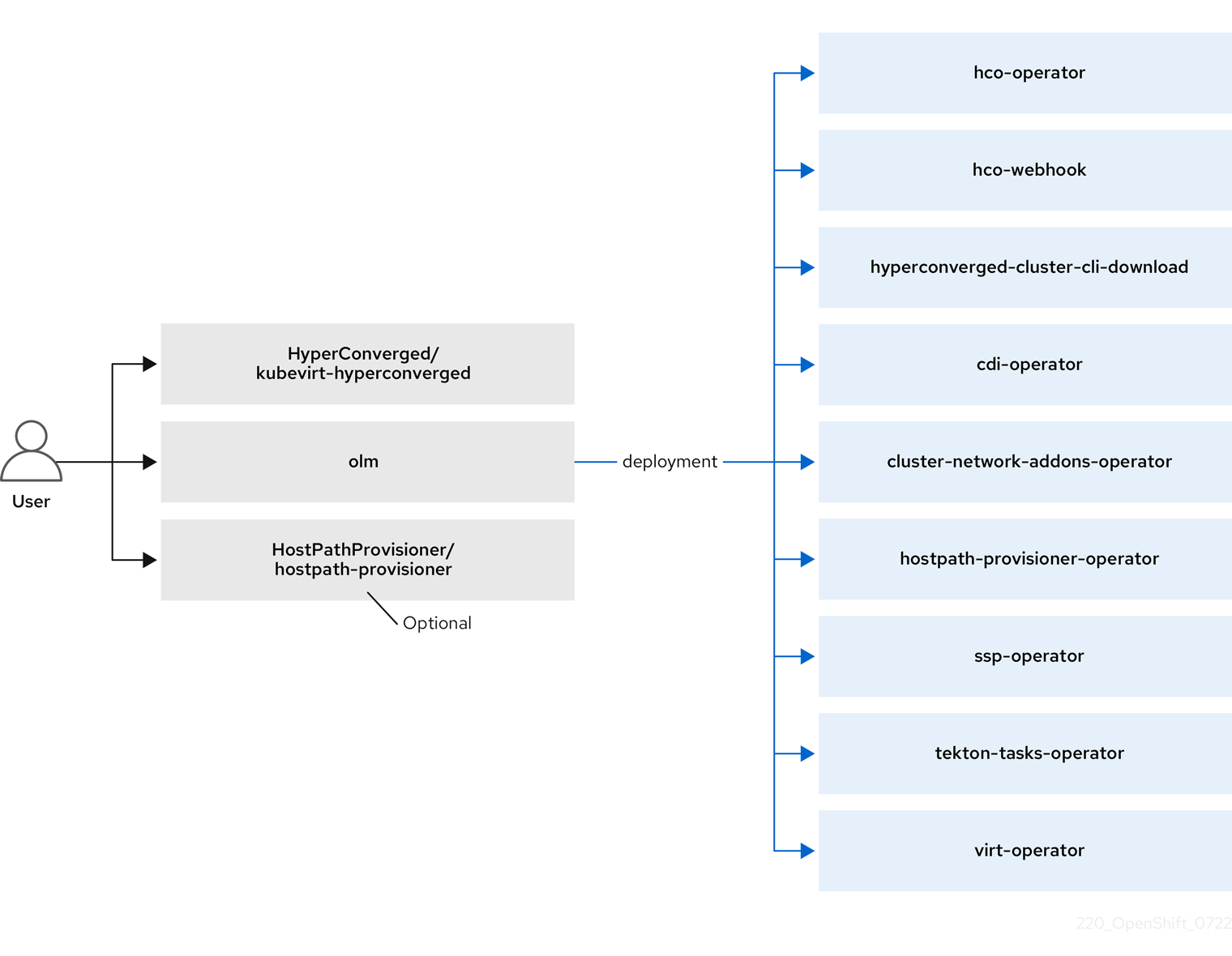
The Operator Lifecycle Manager (OLM) deploys operator pods for each component of OpenShift Virtualization:
-
Compute:
virt-operator -
Storage:
cdi-operator -
Network:
cluster-network-addons-operator -
Scaling:
ssp-operator -
Templating:
tekton-tasks-operator
OLM also deploys the hyperconverged-cluster-operator pod, which is responsible for the deployment, configuration, and life cycle of other components, and several helper pods: hco-webhook, and hyperconverged-cluster-cli-download.
After all operator pods are successfully deployed, you should create the HyperConverged custom resource (CR). The configurations set in the HyperConverged CR serve as the single source of truth and the entrypoint for OpenShift Virtualization, and guide the behavior of the CRs.
The HyperConverged CR creates corresponding CRs for the operators of all other components within its reconciliation loop. Each operator then creates resources such as daemon sets, config maps, and additional components for the OpenShift Virtualization control plane. For example, when the HyperConverged Operator (HCO) creates the KubeVirt CR, the OpenShift Virtualization Operator reconciles it and creates additional resources such as virt-controller, virt-handler, and virt-api.
The OLM deploys the Hostpath Provisioner (HPP) Operator, but it is not functional until you create a hostpath-provisioner CR.
1.3.1. About the HyperConverged Operator (HCO)
The HCO, hco-operator, provides a single entry point for deploying and managing OpenShift Virtualization and several helper operators with opinionated defaults. It also creates custom resources (CRs) for those operators.
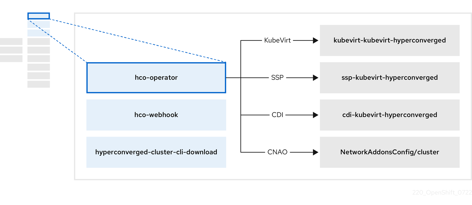
Table 1.7. HyperConverged Operator components
| Component | Description |
|---|---|
|
|
Validates the |
|
|
Provides the |
|
| Contains all operators, CRs, and objects needed by OpenShift Virtualization. |
|
| A Scheduling, Scale, and Performance (SSP) CR. This is automatically created by the HCO. |
|
| A Containerized Data Importer (CDI) CR. This is automatically created by the HCO. |
|
|
A CR that instructs and is managed by the |
1.3.2. About the Containerized Data Importer (CDI) Operator
The CDI Operator, cdi-operator, manages CDI and its related resources, which imports a virtual machine (VM) image into a persistent volume claim (PVC) by using a data volume.
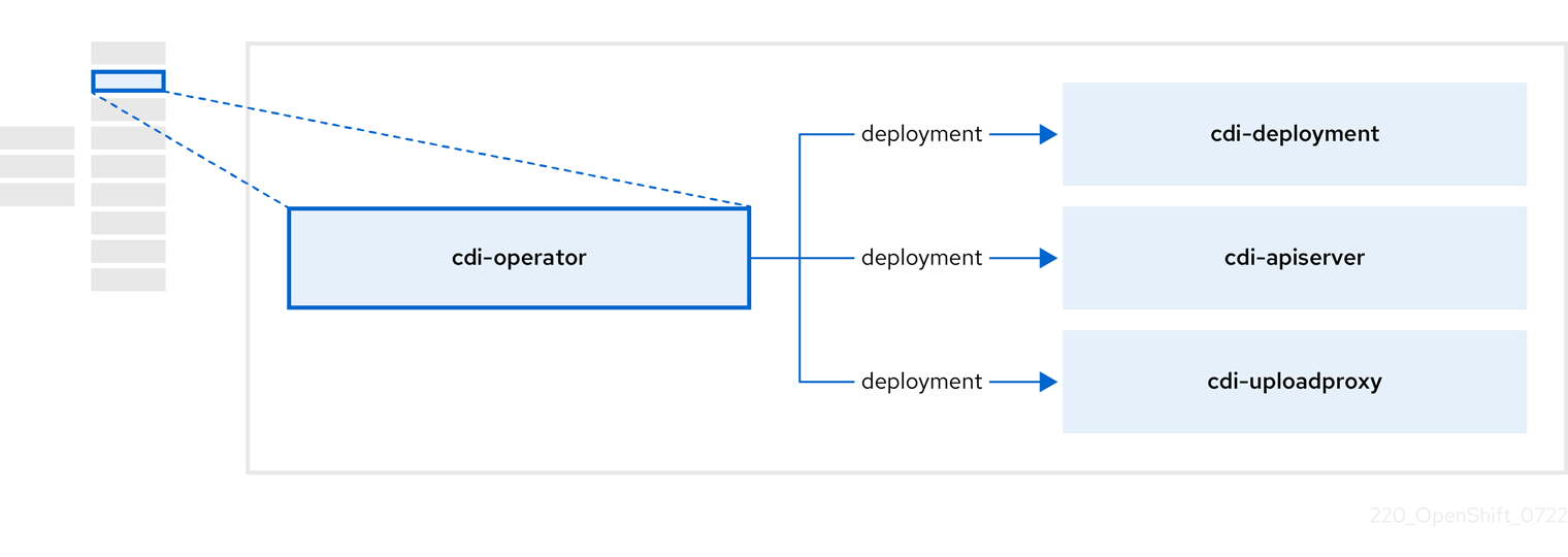
Table 1.8. CDI Operator components
| Component | Description |
|---|---|
|
| Manages the authorization to upload VM disks into PVCs by issuing secure upload tokens. |
|
| Directs external disk upload traffic to the appropriate upload server pod so that it can be written to the correct PVC. Requires a valid upload token. |
|
| Helper pod that imports a virtual machine image into a PVC when creating a data volume. |
1.3.3. About the Cluster Network Addons Operator
The Cluster Network Addons Operator, cluster-network-addons-operator, deploys networking components on a cluster and manages the related resources for extended network functionality.
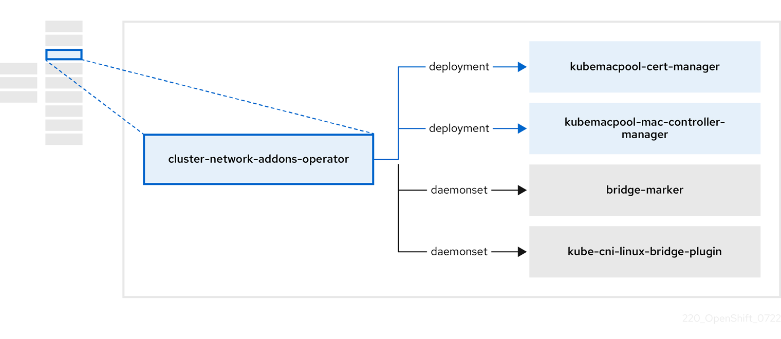
Table 1.9. Cluster Network Addons Operator components
| Component | Description |
|---|---|
|
| Manages TLS certificates of Kubemacpool’s webhooks. |
|
| Provides a MAC address pooling service for virtual machine (VM) network interface cards (NICs). |
|
| Marks network bridges available on nodes as node resources. |
|
| Installs Container Network Interface (CNI) plugins on cluster nodes, enabling the attachment of VMs to Linux bridges through network attachment definitions. |
1.3.4. About the Hostpath Provisioner (HPP) Operator
The HPP Operator, hostpath-provisioner-operator, deploys and manages the multi-node HPP and related resources.
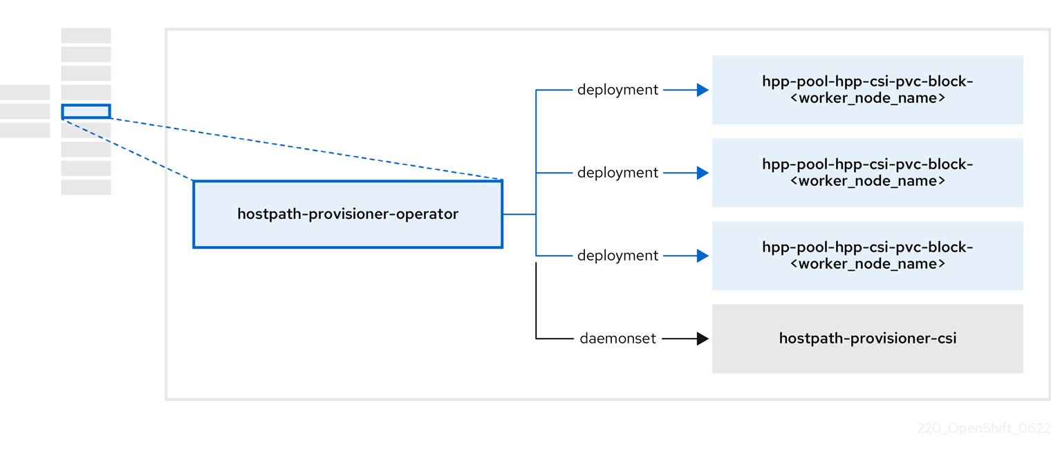
Table 1.10. HPP Operator components
| Component | Description |
|---|---|
|
| Provides a worker for each node where the HPP is designated to run. The pods mount the specified backing storage on the node. |
|
| Implements the Container Storage Interface (CSI) driver interface of the HPP. |
|
| Implements the legacy driver interface of the HPP. |
1.3.5. About the Scheduling, Scale, and Performance (SSP) Operator
The SSP Operator, ssp-operator, deploys the common templates, the related default boot sources, the pipeline tasks, and the template validator.
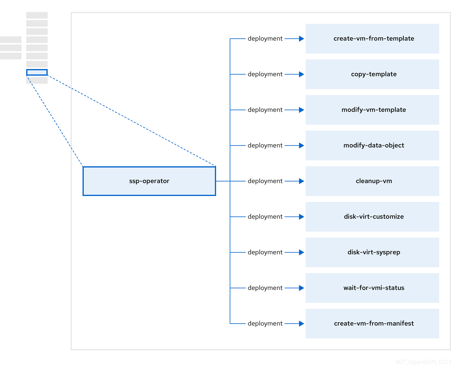
Table 1.11. SSP Operator components
| Component | Description |
|---|---|
|
| Creates a VM from a template. |
|
| Copies a VM template. |
|
| Creates or removes a VM template. |
|
| Creates or removes data volumes or data sources. |
|
| Runs a script or a command on a VM, then stops or deletes the VM afterward. |
|
|
Runs a |
|
|
Runs a |
|
| Waits for a specific virtual machine instance (VMI) status, then fails or succeeds according to that status. |
|
| Creates a VM from a manifest. |
1.3.6. About the OpenShift Virtualization Operator
The OpenShift Virtualization Operator, virt-operator deploys, upgrades, and manages OpenShift Virtualization without disrupting current virtual machine (VM) workloads.
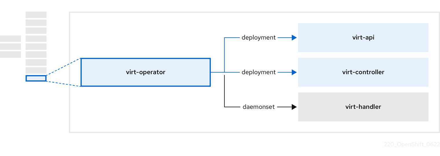
Table 1.12. virt-operator components
| Component | Description |
|---|---|
|
| HTTP API server that serves as the entry point for all virtualization-related flows. |
|
|
Observes the creation of a new VM instance object and creates a corresponding pod. When the pod is scheduled on a node, |
|
|
Monitors any changes to a VM and instructs |
|
|
Contains the VM that was created by the user as implemented by |
Chapter 2. Getting started
2.1. Getting started with OpenShift Virtualization
You can explore the features and functionalities of OpenShift Virtualization by installing and configuring a basic environment.
Cluster configuration procedures require cluster-admin privileges.
2.1.1. Planning and installing OpenShift Virtualization
Plan and install OpenShift Virtualization on an Red Hat OpenShift Service on AWS cluster:
Planning and installation resources
2.1.2. Creating and managing virtual machines
Create a virtual machine (VM):
Create a VM from a Red Hat image.
You can create a VM by using a Red Hat template.
Create a VM from a custom image.
You can create a VM by importing a custom image from a container registry or a web page, by uploading an image from your local machine, or by cloning a persistent volume claim (PVC).
Connect a VM to a secondary network:
Open Virtual Network (OVN)-Kubernetes secondary network.
NoteVMs are connected to the pod network by default.
Connect to a VM:
- Connect to the serial console or VNC console of a VM.
- Connect to a VM by using SSH.
- Connect to the desktop viewer for Windows VMs.
Manage a VM:
2.1.3. Next steps
2.2. Using the virtctl and libguestfs CLI tools
You can manage OpenShift Virtualization resources by using the virtctl command line tool.
You can access and modify virtual machine (VM) disk images by using the libguestfs command line tool. You deploy libguestfs by using the virtctl libguestfs command.
2.2.1. Installing virtctl
To install virtctl on Red Hat Enterprise Linux (RHEL) 9, Linux, Windows, and MacOS operating systems, you download and install the virtctl binary file.
To install virtctl on RHEL 8, you enable the OpenShift Virtualization repository and then install the kubevirt-virtctl package.
2.2.1.1. Installing the virtctl binary on RHEL 9, Linux, Windows, or macOS
You can download the virtctl binary for your operating system from the Red Hat OpenShift Service on AWS web console and then install it.
Procedure
- Navigate to the Virtualization → Overview page in the web console.
-
Click the Download virtctl link to download the
virtctlbinary for your operating system. Install
virtctl:For RHEL 9 and other Linux operating systems:
Decompress the archive file:
$ tar -xvf <virtctl-version-distribution.arch>.tar.gz
Run the following command to make the
virtctlbinary executable:$ chmod +x <path/virtctl-file-name>
Move the
virtctlbinary to a directory in yourPATHenvironment variable.You can check your path by running the following command:
$ echo $PATH
Set the
KUBECONFIGenvironment variable:$ export KUBECONFIG=/home/<user>/clusters/current/auth/kubeconfig
For Windows:
- Decompress the archive file.
-
Navigate the extracted folder hierarchy and double-click the
virtctlexecutable file to install the client. Move the
virtctlbinary to a directory in yourPATHenvironment variable.You can check your path by running the following command:
C:\> path
For macOS:
- Decompress the archive file.
Move the
virtctlbinary to a directory in yourPATHenvironment variable.You can check your path by running the following command:
echo $PATH
2.2.1.2. Installing the virtctl RPM on RHEL 8
You can install the virtctl RPM package on Red Hat Enterprise Linux (RHEL) 8 by enabling the OpenShift Virtualization repository and installing the kubevirt-virtctl package.
Prerequisites
- Each host in your cluster must be registered with Red Hat Subscription Manager (RHSM) and have an active Red Hat OpenShift Service on AWS subscription.
Procedure
Enable the OpenShift Virtualization repository by using the
subscription-managerCLI tool to run the following command:# subscription-manager repos --enable cnv-4.15-for-rhel-8-x86_64-rpms
Install the
kubevirt-virtctlpackage by running the following command:# yum install kubevirt-virtctl
2.2.2. virtctl commands
The virtctl client is a command-line utility for managing OpenShift Virtualization resources.
The virtual machine (VM) commands also apply to virtual machine instances (VMIs) unless otherwise specified.
2.2.2.1. virtctl information commands
You use virtctl information commands to view information about the virtctl client.
Table 2.1. Information commands
| Command | Description |
|---|---|
|
|
View the |
|
|
View a list of |
|
| View a list of options for a specific command. |
|
|
View a list of global command options for any |
2.2.2.2. VM information commands
You can use virtctl to view information about virtual machines (VMs) and virtual machine instances (VMIs).
Table 2.2. VM information commands
| Command | Description |
|---|---|
|
| View the file systems available on a guest machine. |
|
| View information about the operating systems on a guest machine. |
|
| View the logged-in users on a guest machine. |
2.2.2.3. VM management commands
You use virtctl virtual machine (VM) management commands to manage and migrate virtual machines (VMs) and virtual machine instances (VMIs).
Table 2.3. VM management commands
| Command | Description |
|---|---|
|
|
Create a |
|
| Start a VM. |
|
| Start a VM in a paused state. This option enables you to interrupt the boot process from the VNC console. |
|
| Stop a VM. |
|
| Force stop a VM. This option might cause data inconsistency or data loss. |
|
| Pause a VM. The machine state is kept in memory. |
|
| Unpause a VM. |
|
| Migrate a VM. |
|
| Cancel a VM migration. |
|
| Restart a VM. |
|
|
Create an |
|
|
Create a |
2.2.2.4. VM connection commands
You use virtctl connection commands to expose ports and connect to virtual machines (VMs) and virtual machine instances (VMIs).
Table 2.4. VM connection commands
| Command | Description |
|---|---|
|
| Connect to the serial console of a VM. |
|
| Create a service that forwards a designated port of a VM and expose the service on the specified port of the node.
Example: |
|
| Copy a file from your machine to a VM. This command uses the private key of an SSH key pair. The VM must be configured with the public key. |
|
| Copy a file from a VM to your machine. This command uses the private key of an SSH key pair. The VM must be configured with the public key. |
|
| Open an SSH connection with a VM. This command uses the private key of an SSH key pair. The VM must be configured with the public key. |
|
| Connect to the VNC console of a VM.
You must have |
|
| Display the port number and connect manually to a VM by using any viewer through the VNC connection. |
|
| Specify a port number to run the proxy on the specified port, if that port is available. If a port number is not specified, the proxy runs on a random port. |
2.2.2.5. VM export commands
Use virtctl vmexport commands to create, download, or delete a volume exported from a VM, VM snapshot, or persistent volume claim (PVC). Certain manifests also contain a header secret, which grants access to the endpoint to import a disk image in a format that OpenShift Virtualization can use.
Table 2.5. VM export commands
| Command | Description |
|---|---|
|
|
Create a
|
|
|
Delete a |
|
|
Download the volume defined in a
Optional:
|
|
|
Create a |
|
| Retrieve the manifest for an existing export. The manifest does not include the header secret. |
|
| Create a VM export for a VM example, and retrieve the manifest. The manifest does not include the header secret. |
|
| Create a VM export for a VM snapshot example, and retrieve the manifest. The manifest does not include the header secret. |
|
| Retrieve the manifest for an existing export. The manifest includes the header secret. |
|
| Retrieve the manifest for an existing export in json format. The manifest does not include the header secret. |
|
| Retrieve the manifest for an existing export. The manifest includes the header secret and writes it to the file specified. |
2.2.2.6. VM memory dump commands
You can use the virtctl memory-dump command to output a VM memory dump on a PVC. You can specify an existing PVC or use the --create-claim flag to create a new PVC.
Prerequisites
-
The PVC volume mode must be
FileSystem. The PVC must be large enough to contain the memory dump.
The formula for calculating the PVC size is
(VMMemorySize + 100Mi) * FileSystemOverhead, where100Miis the memory dump overhead.You must enable the hot plug feature gate in the
HyperConvergedcustom resource by running the following command:$ oc patch hyperconverged kubevirt-hyperconverged -n openshift-cnv \ --type json -p '[{"op": "add", "path": "/spec/featureGates", \ "value": "HotplugVolumes"}]'
Downloading the memory dump
You must use the virtctl vmexport download command to download the memory dump:
$ virtctl vmexport download <vmexport_name> --vm|pvc=<object_name> \
  --volume=<volume_name> --output=<output_file>
Table 2.6. VM memory dump commands
| Command | Description |
|---|---|
|
|
Save the memory dump of a VM on a PVC. The memory dump status is displayed in the Optional:
|
|
|
Rerun the This command overwrites the previous memory dump. |
|
| Remove a memory dump. You must remove a memory dump manually if you want to change the target PVC.
This command removes the association between the VM and the PVC, so that the memory dump is not displayed in the |
2.2.2.7. Hot plug and hot unplug commands
You use virtctl to add or remove resources from running virtual machines (VMs) and virtual machine instances (VMIs).
Table 2.7. Hot plug and hot unplug commands
| Command | Description |
|---|---|
|
| Hot plug a data volume or persistent volume claim (PVC). Optional:
|
|
| Hot unplug a virtual disk. |
|
| Hot plug a Linux bridge network interface. |
|
| Hot unplug a Linux bridge network interface. |
2.2.2.8. Image upload commands
You use the virtctl image-upload commands to upload a VM image to a data volume.
Table 2.8. Image upload commands
| Command | Description |
|---|---|
|
| Upload a VM image to a data volume that already exists. |
|
| Upload a VM image to a new data volume of a specified requested size. |
2.2.3. Deploying libguestfs by using virtctl
You can use the virtctl guestfs command to deploy an interactive container with libguestfs-tools and a persistent volume claim (PVC) attached to it.
Procedure
To deploy a container with
libguestfs-tools, mount the PVC, and attach a shell to it, run the following command:$ virtctl guestfs -n <namespace> <pvc_name> 1- 1
- The PVC name is a required argument. If you do not include it, an error message appears.
2.2.3.1. Libguestfs and virtctl guestfs commands
Libguestfs tools help you access and modify virtual machine (VM) disk images. You can use libguestfs tools to view and edit files in a guest, clone and build virtual machines, and format and resize disks.
You can also use the virtctl guestfs command and its sub-commands to modify, inspect, and debug VM disks on a PVC. To see a complete list of possible sub-commands, enter virt- on the command line and press the Tab key. For example:
| Command | Description |
|---|---|
|
| Edit a file interactively in your terminal. |
|
| Inject an ssh key into the guest and create a login. |
|
| See how much disk space is used by a VM. |
|
| See the full list of all RPMs installed on a guest by creating an output file containing the full list. |
|
|
Display the output file list of all RPMs created using the |
|
| Seal a virtual machine disk image to be used as a template. |
By default, virtctl guestfs creates a session with everything needed to manage a VM disk. However, the command also supports several flag options if you want to customize the behavior:
| Flag Option | Description |
|---|---|
|
|
Provides help for |
|
| To use a PVC from a specific namespace.
If you do not use the
If you do not include a |
|
|
Lists the
You can configure the container to use a custom image by using the |
|
|
Indicates that
By default,
If a cluster does not have any
If not set, the |
|
|
Shows the pull policy for the
You can also overwrite the image’s pull policy by setting the |
The command also checks if a PVC is in use by another pod, in which case an error message appears. However, once the libguestfs-tools process starts, the setup cannot avoid a new pod using the same PVC. You must verify that there are no active virtctl guestfs pods before starting the VM that accesses the same PVC.
The virtctl guestfs command accepts only a single PVC attached to the interactive pod.
2.3. Web console overview
The Virtualization section of the Red Hat OpenShift Service on AWS web console contains the following pages for managing and monitoring your OpenShift Virtualization environment.
Table 2.9. Virtualization pages
| Page | Description |
|---|---|
| Manage and monitor the OpenShift Virtualization environment. | |
| Create virtual machines from a catalog of templates. | |
| Create and manage virtual machines. | |
| Create and manage templates. | |
| Create and manage virtual machine instance types. | |
| Create and manage virtual machine preferences. | |
| Create and manage DataSources for bootable volumes. | |
| Create and manage migration policies for workloads. | |
| Run network latency and storage checkups for virtual machines. |
Table 2.10. Key
| Icon | Description |
|---|---|
|
| Edit icon |
|
| Link icon |
|
| Start VM icon |
|
| Stop VM icon |
|
| Restart VM icon |
|
| Pause VM icon |
|
| Unpause VM icon |
2.3.1. Overview page
The Overview page displays resources, metrics, migration progress, and cluster-level settings.
Example 2.1. Overview page
| Element | Description |
|---|---|
|
Download virtctl |
Download the |
| Resources, usage, alerts, and status. | |
| Top consumers of CPU, memory, and storage resources. | |
| Status of live migrations. | |
| The Settings tab contains the Cluster tab, User tab, and Preview features tab. | |
| Settings → Cluster tab | OpenShift Virtualization version, update status, live migration, templates project, load balancer service, guest management, resource management, and SCSI persistent reservation settings. |
| Settings → User tab | Public SSH keys, user permissions, and welcome information settings. |
| Settings → Preview features | Enable select preview features in the web console. Features in this tab change frequently. Preview features are disabled by default and must not be enabled in production environments. |
2.3.1.1. Overview tab
The Overview tab displays resources, usage, alerts, and status.
Example 2.2. Overview tab
| Element | Description |
|---|---|
| Getting started resources card |
|
| Memory tile | Memory usage, with a chart showing the last 1 day’s trend. |
| Storage tile | Storage usage, with a chart showing the last 1 day’s trend. |
| vCPU usage tile | vCPU usage, with a chart showing the last 1 day’s trend. |
| VirtualMachines tile | Number of virtual machines, with a chart showing the last 1 day’s trend. |
| Alerts tile | OpenShift Virtualization alerts, grouped by severity. |
| VirtualMachine statuses tile | Number of virtual machines, grouped by status. |
| VirtualMachines per resource chart | Number of virtual machines created from templates and instance types. |
2.3.1.2. Top consumers tab
The Top consumers tab displays the top consumers of CPU, memory, and storage.
Example 2.3. Top consumers tab
| Element | Description |
|---|---|
|
View virtualization dashboard | Link to Observe → Dashboards, which displays the top consumers for OpenShift Virtualization. |
| Time period list | Select a time period to filter the results. |
| Top consumers list | Select the number of top consumers to filter the results. |
| CPU chart | Virtual machines with the highest CPU usage. |
| Memory chart | Virtual machines with the highest memory usage. |
| Memory swap traffic chart | Virtual machines with the highest memory swap traffic. |
| vCPU wait chart | Virtual machines with the highest vCPU wait periods. |
| Storage throughput chart | Virtual machines with the highest storage throughput usage. |
| Storage IOPS chart | Virtual machines with the highest storage input/output operations per second usage. |
2.3.1.3. Migrations tab
The Migrations tab displays the status of virtual machine migrations.
Example 2.4. Migrations tab
| Element | Description |
|---|---|
| Time period list | Select a time period to filter virtual machine migrations. |
| VirtualMachineInstanceMigrations information table | List of virtual machine migrations. |
2.3.1.4. Settings tab
The Settings tab displays cluster-wide settings.
Example 2.5. Tabs on the Settings tab
| Tab | Description |
|---|---|
| OpenShift Virtualization version, update status, live migration, templates project, load balancer service, guest management, resource management, and SCSI persistent reservation settings. | |
| Public SSH key management, user permissions, and welcome information settings. | |
| Enable select preview features in the web console. These features change frequently. |
2.3.1.4.1. Cluster tab
The Cluster tab displays the OpenShift Virtualization version and update status. You configure live migration and other settings on the Cluster tab.
Example 2.6. Cluster tab
| Element | Description |
|---|---|
| Installed version | OpenShift Virtualization version. |
| Update status | OpenShift Virtualization update status. |
| Channel | OpenShift Virtualization update channel. |
| General Settings section | Expand this section to configure the Live migration settings, the SSH configuration settings, and the Template project settings. |
| General Settings → Live Migration section | Expand this section to configure live migration settings. |
| General Settings → Live Migration → Max. migrations per cluster field | Select the maximum number of live migrations per cluster. |
| General Settings → Live Migration → Max. migrations per node field | Select the maximum number of live migrations per node. |
| General Settings → Live Migration → Live migration network list | Select a dedicated secondary network for live migration. |
| General Settings → SSH Configuration → SSH over LoadBalancer service switch | Enable the creation of LoadBalancer services for SSH connections to VMs. You must configure a load balancer. |
| General Settings → SSH Configuration → SSH over NodePort service switch | Allow the creation of node port services for SSH connections to virtual machines. |
| General Settings → Template project section |
Expand this section to select a project for Red Hat templates. The default project is To store Red Hat templates in multiple projects, clone the template and then select a project for the cloned template. |
| Guest Management | Expand this section to configure the Automatic subscription of new RHEL VirtualMachines settings and the Enable guest system log access switch. |
| Guest Management → Automatic subscription of new RHEL VirtualMachines | Expand this section to enable automatic subscription for Red Hat Enterprise Linux (RHEL) virtual machines and guest system log access. To enable this feature, you need cluster administrator permissions, an organization ID, and an activation key. |
| Guest Management → Automatic subscription of new RHEL VirtualMachines → Activation Key field | Enter the activation key. |
| Guest Management → Automatic subscription of new RHEL VirtualMachines → Organization ID field | Enter the organization ID. |
| Guest Management → Automatic subscription of new RHEL VirtualMachines → Enable auto updates for RHEL VirtualMachines switch | Enable the automatic pulling of updates from the RHEL repository. To enable this feature, you need an activation key and organization ID. |
| Guest Management → Enable guest system log access switch | Enable access to the virtual machine’s guest system log. |
| Resource Management | Expand this section to configure the Auto-compute CPU limits settings and the Kernel Samepage Merging (KSM) switch. |
| Resource Management → Auto-compute CPU limits | Enable automatic computing CPU limits on projects containing labels. |
| Resource Management → Kernel Samepage Merging (KSM) | Enable KSM for all nodes in the cluster. |
| SCSI Persistent Reservation | Expand this section to configure the Enable persistent reservation switch. |
| SCSI Persistent Reservation → Enable persistent reservation | Enable SCSI reservation for disks. This option must be used only for cluster-aware applications. |
2.3.1.4.2. User tab
You view user permissions and manage public SSH keys and welcome information on the User tab.
Example 2.7. User tab
| Element | Description |
|---|---|
| Manage SSH keys section | Expand this section to add public SSH keys to a project. The keys are added automatically to all virtual machines that you subsequently create in the selected project. |
| Permissions section | Expand this section to view cluster-wide user permissions. |
| Welcome information section | Expand this section to show or hide the Welcome information dialog. |
2.3.1.4.3. Preview features tab
Enable select preview features in the web console. Features in this tab change frequently.
2.3.2. Catalog page
You create a virtual machine from a template or instance type on the Catalog page.
Example 2.8. Catalog page
| Element | Description |
|---|---|
| Displays bootable volumes and instance types for creating a virtual machine. | |
| Displays a catalog of templates for creating a virtual machine. |
2.3.2.1. InstanceTypes tab
You create a virtual machine from an instance type on the InstanceTypes tab.
| Element | Description |
|---|---|
| Add volume button | Click to upload a volume or to use an existing persistent volume claim, volume snapshot, or data source. |
| Volumes project field |
Project in which bootable volumes are stored. The default is |
| Filter field | Filter boot sources by operating system or resource. |
| Search field | Search boot sources by name. |
| Manage columns icon | Select up to 9 columns to display in the table. |
| Volume table | Select a bootable volume for your virtual machine. |
| Red Hat provided tab | Select an instance type provided by Red Hat. |
| User provided tab | Select an instance type that you created on the InstanceType page. |
| VirtualMachine details pane | Displays the virtual machine settings. |
| Name field | Optional: Enter the virtual machine name. |
| Storage class field | Select a storage class. |
| Public SSH key | Click the edit icon to add a new or existing public SSH key. |
| Dynamic SSH key injection switch | Enable dynamic SSH key injection. Only RHEL supports dynamic SSH key injection. |
| Start this VirtualMachine after creation checkbox | Clear this checkbox to prevent the virtual machine from starting automatically. |
| Create VirtualMachine button | Creates a virtual machine. |
| View YAML & CLI button |
Displays the YAML configuration file and the |
2.3.2.2. Template catalog tab
You select a template on the Template catalog tab to create a virtual machine.
Example 2.9. Template catalog tab
| Element | Description |
|---|---|
| Template project list | Select the project in which Red Hat templates are located.
By default, Red Hat templates are stored in the |
| All items | Default templates | User templates | Click All items to display all available templates, Default templates to display the default templates, and User templates to display the user created templates. |
| Boot source available checkbox | Select the checkbox to display templates with an available boot source. |
| Operating system checkboxes | Select checkboxes to display templates with selected operating systems. |
| Workload checkboxes | Select checkboxes to display templates with selected workloads. |
| Search field | Search templates by keyword. |
| Template tiles | Click a template tile to view template details and to create a virtual machine. |
2.3.3. VirtualMachines page
You create and manage virtual machines on the VirtualMachines page.
Example 2.10. VirtualMachines page
| Element | Description |
|---|---|
| Create button | Create a virtual machine from a template, volume, or YAML configuration file. |
| Filter field | Filter virtual machines by status, template, operating system, or node. |
| Search field | Search for virtual machines by name, label, or IP address. |
| Manage columns icon | Select up to 9 columns to display in the table. The Namespace column is displayed only when All Projects is selected from the Projects list. |
| Virtual machines table | List of virtual machines.
Click the actions menu
Click a virtual machine to navigate to the VirtualMachine details page. |
2.3.3.1. VirtualMachine details page
You configure a virtual machine on the Configuration tab of the VirtualMachine details page.
Example 2.11. VirtualMachine details page
| Element | Description |
|---|---|
| Actions menu | Click the Actions menu to select Stop, Restart, Pause, Clone, Migrate, Copy SSH command, Edit labels, Edit annotations, or Delete. If you select Stop, Force stop replaces Stop in the action menu. Use Force stop to initiate an immediate shutdown if the operating system becomes unresponsive. |
| Resource usage, alerts, disks, and devices. | |
| Memory, CPU, storage, network, and migration metrics. | |
| Virtual machine YAML configuration file. | |
| Contains the Details, Storage, Network, Scheduling, SSH, Initial run, and Metadata tabs. | |
| Configure the VirtualMachine details of the VM. | |
| Configure the storage of the VM. | |
| Configure the network of the VM. | |
| Configure the schedule of a VM to run on specific nodes. | |
| Configure the SSH settings of the VM. | |
| Configure the cloud-init settings for the VM, or the Sysprep settings if the VM is Windows. | |
| Configure label and annotation metadata of the VM. | |
| View list of virtual machine events. | |
| Open a console session to the virtual machine. | |
| Create snapshots and restore virtual machines from snapshots. | |
| View status conditions and volume snapshot statuses. |
2.3.3.1.1. Overview tab
The Overview tab displays resource usage, alerts, and configuration information.
Example 2.12. Overview tab
| Element | Description |
|---|---|
| Details tile | General virtual machine information. |
| Utilization tile | CPU, Memory, Storage, and Network transfer charts. By default, Network transfer displays the sum of all networks. To view the breakdown for a specific network, click Breakdown by network. |
| Hardware devices tile | GPU and host devices. |
| File systems tile | File system information. This information is provided by the guest agent. |
| Services tile | List of services. |
| Active users tile | List of active users. |
| Alerts tile | OpenShift Virtualization alerts, grouped by severity. |
| General tile | Namespace, Node, VirtualMachineInstance, Pod, and Owner information. |
| Snapshots tile |
Take snapshot |
| Network interfaces tile | Network interfaces table. |
| Disks tile | Disks table. |
2.3.3.1.2. Metrics tab
The Metrics tab displays memory, CPU, network, storage, and migration usage charts, as well as live migration progress.
Example 2.13. Metrics tab
| Element | Description |
|---|---|
| Time range list | Select a time range to filter the results. |
|
Virtualization dashboard | Link to the Workloads tab of the current project. |
| Utilization | Memory and CPU charts. |
| Storage | Storage total read/write and Storage IOPS total read/write charts. |
| Network | Network in, Network out, Network bandwidth, and Network interface charts. Select All networks or a specific network from the Network interface list. |
| Migration | Migration and KV data transfer rate charts. |
| LiveMigration progress | LiveMigration completion status. |
2.3.3.1.3. YAML tab
You configure the virtual machine by editing the YAML file on the YAML tab.
Example 2.14. YAML tab
| Element | Description |
|---|---|
| Save button | Save changes to the YAML file. |
| Reload button | Discard your changes and reload the YAML file. |
| Cancel button | Exit the YAML tab. |
| Download button | Download the YAML file to your local machine. |
2.3.3.1.4. Configuration tab
You configure scheduling, network interfaces, disks, and other options on the Configuration tab.
Example 2.15. Tabs on the Configuration tab
| Element | Description |
|---|---|
| Search field | Search configurations by keyword. |
| Virtual machine details. | |
| Configure the storage of the VM. | |
| Configure the network of the VM. | |
| Configure the schedule of a VM to run on specific nodes. | |
| Configure the SSH settings of the VM. | |
| Configure the cloud-init settings for the VM, or the Sysprep settings if the VM is Windows. | |
| Configure label and annotation metadata of the VM. |
2.3.3.1.4.1. Details tab
You manage the VM details on the Details tab.
Example 2.16. Details tab
| Setting | Description |
|---|---|
| Description | Click the edit icon to enter a description. |
| Workload profile | Click the edit icon to edit the workload profile. |
| CPU | Memory | Click the edit icon to edit the CPU | Memory request. Restart the virtual machine to apply the change. |
| Hostname | Hostname of the virtual machine. Restart the virtual machine to apply the change. |
| Headless mode | Enable headless mode. Restart the virtual machine to apply the change. |
| Guest system log access | Enable guest system log access. |
| Hardware devices | Manage GPU and host devices. |
| Boot management | Change the boot mode and order, and enable Start in pause mode. |
2.3.3.1.4.2. Storage tab
You manage the disks and environment of the VM on the Storage tab.
Example 2.17. Storage tab
| Setting | Description |
|---|---|
| Add disk button | Add a disk to the virtual machine. |
| Filter field | Filter by disk type. |
| Search field | Search for a disk by name. |
| Mount Windows drivers disk checkbox |
Select to mount a |
| Disks table | List of virtual machine disks.
Click the actions menu
|
| Add Config Map, Secret or Service Account | Click the link and select a config map, secret, or service account from the resource list. |
2.3.3.1.4.3. Network tab
You manage network interfaces on the Network tab.
Example 2.18. Network interfaces table
| Setting | Description |
|---|---|
| Add network interface button | Add a network interface to the virtual machine. |
| Filter field | Filter by interface type. |
| Search field | Search for a network interface by name or by label. |
| Network interface table | List of network interfaces.
Click the actions menu
|
2.3.3.1.4.4. Scheduling tab
You configure virtual machines to run on specific nodes on the Scheduling tab.
Restart the virtual machine to apply changes.
Example 2.19. Scheduling tab
| Setting | Description |
|---|---|
| Node selector | Click the edit icon to add a label to specify qualifying nodes. |
| Tolerations | Click the edit icon to add a toleration to specify qualifying nodes. |
| Affinity rules | Click the edit icon to add an affinity rule. |
| Descheduler switch | Enable or disable the descheduler. The descheduler evicts a running pod so that the pod can be rescheduled onto a more suitable node. This field is disabled if the virtual machine cannot be live migrated. |
| Dedicated resources | Click the edit icon to select Schedule this workload with dedicated resources (guaranteed policy). |
| Eviction strategy | Click the edit icon to select LiveMigrate as the virtual machine eviction strategy. |
2.3.3.1.4.5. SSH tab
You configure the SSH details on the SSH tab.
Example 2.20. SSH tab
| Setting | Description |
|---|---|
| SSH access section | Expand this section to configure SSH using virtctl and SSH service type. |
| Public SSH key section | Expand this section to configure public SSH keys and dynamic SSH public key injection. |
2.3.3.1.4.6. Initial run
You manage cloud-init settings or configure Sysprep for Windows virtual machines on the Initial run tab.
Restart the virtual machine to apply changes.
Example 2.21. Initial run tab
| Element | Description |
|---|---|
| Cloud-init | Click the edit icon to edit the cloud-init settings. |
| Sysprep |
Click the edit icon to upload an |
2.3.3.1.4.7. Metadata tab
You configure the labels and annotations on the Metadata tab.
Example 2.22. Metadata tab
| Element | Description |
|---|---|
| Labels | Click the edit icon to manage your labels. |
| Annotations | Click the edit icon to manage annotations. |
2.3.3.1.5. Events tab
The Events tab displays a list of virtual machine events.
2.3.3.1.6. Console tab
You can open a console session to the virtual machine on the Console tab.
Example 2.23. Console tab
| Element | Description |
|---|---|
| Guest login credentials section |
Expand Guest login credentials to view the credentials created with |
| Console list | Select VNC console or Serial console. The Desktop viewer option is displayed for Windows virtual machines. You must install an RDP client on a machine on the same network. |
| Send key list | Select a key-stroke combination to send to the console. |
| Paste button | Paste a string from your clipboard to the VNC console. |
| Disconnect button | Disconnect the console connection. You must manually disconnect the console connection if you open a new console session. Otherwise, the first console session continues to run in the background. |
2.3.3.1.7. Snapshots tab
You can create a snapshot, create a copy of a virtual machine from a snapshot, restore a snapshot, edit labels or annotations, and edit or delete volume snapshots on the Snapshots tab.
Example 2.24. Snapshots tab
| Element | Description |
|---|---|
| Take snapshot button | Create a snapshot. |
| Filter field | Filter snapshots by status. |
| Search field | Search for snapshots by name or by label. |
| Snapshot table | List of snapshots Click the snapshot name to edit the labels or annotations.
Click the actions menu
|
2.3.3.1.8. Diagnostics tab
You view the status conditions and volume snapshot status on the Diagnostics tab.
Example 2.25. Diagnostics tab
| Element | Description |
|---|---|
| Status conditions table | Display a list of conditions that are reported for the virtual machine. |
| Filter field | Filter status conditions by category and condition. |
| Search field | Search status conditions by reason. |
| Manage columns icon | Select up to 9 columns to display in the table. |
| Volume snapshot status table | List of volumes, their snapshot enablement status, and reason. |
| DataVolume status table | List of data volumes and their Phase and Progress values. |
2.3.4. Templates page
You create, edit, and clone virtual machine templates on the VirtualMachine Templates page.
You cannot edit a Red Hat template. However, you can clone a Red Hat template and edit it to create a custom template.
Example 2.26. VirtualMachine Templates page
| Element | Description |
|---|---|
| Create Template button | Create a template by editing a YAML configuration file. |
| Filter field | Filter templates by type, boot source, template provider, or operating system. |
| Search field | Search for templates by name or by label. |
| Manage columns icon | Select up to 9 columns to display in the table. The Namespace column is only displayed when All Projects is selected from the Projects list. |
| Virtual machine templates table | List of virtual machine templates.
Click the actions menu
|
2.3.4.1. Template details page
You view template settings and edit custom templates on the Template details page.
Example 2.27. Template details page
| Element | Description |
|---|---|
| YAML switch | Set to ON to view your live changes in the YAML configuration file. |
| Actions menu | Click the Actions menu to select Edit, Clone, Edit boot source, Edit boot source reference, Edit labels, Edit annotations, or Delete. |
| Template settings and configurations. | |
| YAML configuration file. | |
| Scheduling configurations. | |
| Network interface management. | |
| Disk management. | |
| Cloud-init, SSH key, and Sysprep management. | |
| Name and cloud user password management. |
2.3.4.1.1. Details tab
You configure a custom template on the Details tab.
Example 2.28. Details tab
| Element | Description |
|---|---|
| Name | Template name. |
| Namespace | Template namespace. |
| Labels | Click the edit icon to edit the labels. |
| Annotations | Click the edit icon to edit the annotations. |
| Display name | Click the edit icon to edit the display name. |
| Description | Click the edit icon to enter a description. |
| Operating system | Operating system name. |
| CPU|Memory | Click the edit icon to edit the CPU|Memory request.
The number of CPUs is calculated by using the following formula: |
| Machine type | Template machine type. |
| Boot mode | Click the edit icon to edit the boot mode. |
| Base template | Name of the base template used to create this template. |
| Created at | Template creation date. |
| Owner | Template owner. |
| Boot order | Template boot order. |
| Boot source | Boot source availability. |
| Provider | Template provider. |
| Support | Template support level. |
| GPU devices | Click the edit icon to add a GPU device. |
| Host devices | Click the edit icon to add a host device. |
| Headless mode | Click the edit icon to set headless mode to ON and to disable VNC console. |
2.3.4.1.2. YAML tab
You configure a custom template by editing the YAML file on the YAML tab.
Example 2.29. YAML tab
| Element | Description |
|---|---|
| Save button | Save changes to the YAML file. |
| Reload button | Discard your changes and reload the YAML file. |
| Cancel button | Exit the YAML tab. |
| Download button | Download the YAML file to your local machine. |
2.3.4.1.3. Scheduling tab
You configure scheduling on the Scheduling tab.
Example 2.30. Scheduling tab
| Setting | Description |
|---|---|
| Node selector | Click the edit icon to add a label to specify qualifying nodes. |
| Tolerations | Click the edit icon to add a toleration to specify qualifying nodes. |
| Affinity rules | Click the edit icon to add an affinity rule. |
| Descheduler switch | Enable or disable the descheduler. The descheduler evicts a running pod so that the pod can be rescheduled onto a more suitable node. |
| Dedicated resources | Click the edit icon to select Schedule this workload with dedicated resources (guaranteed policy). |
| Eviction strategy | Click the edit icon to select LiveMigrate as the virtual machine eviction strategy. |
2.3.4.1.4. Network interfaces tab
You manage network interfaces on the Network interfaces tab.
Example 2.31. Network interfaces tab
| Setting | Description |
|---|---|
| Add network interface button | Add a network interface to the template. |
| Filter field | Filter by interface type. |
| Search field | Search for a network interface by name or by label. |
| Network interface table | List of network interfaces.
Click the actions menu
|
2.3.4.1.5. Disks tab
You manage disks on the Disks tab.
Example 2.32. Disks tab
| Setting | Description |
|---|---|
| Add disk button | Add a disk to the template. |
| Filter field | Filter by disk type. |
| Search field | Search for a disk by name. |
| Disks table | List of template disks.
Click the actions menu
|
2.3.4.1.6. Scripts tab
You manage the cloud-init settings, SSH keys, and Sysprep answer files on the Scripts tab.
Example 2.33. Scripts tab
| Element | Description |
|---|---|
| Cloud-init | Click the edit icon to edit the cloud-init settings. |
| Public SSH key | Click the edit icon to create a new secret or to attach an existing secret to a Linux virtual machine. |
| Sysprep |
Click the edit icon to upload an |
2.3.4.1.7. Parameters tab
You edit selected template settings on the Parameters tab.
Example 2.34. Parameters tab
| Element | Description |
|---|---|
| NAME | Set the name parameters for a virtual machine created from this template. |
| CLOUD_USER_PASSWORD | Set the cloud user password parameters for a virtual machine created from this template. |
2.3.5. InstanceTypes page
You view and manage virtual machine instance types on the InstanceTypes page.
Example 2.35. VirtualMachineClusterInstancetypes page
| Element | Description |
|---|---|
| Create button | Create an instance type by editing a YAML configuration file. |
| Search field | Search for an instance type by name or by label. |
| Manage columns icon | Select up to 9 columns to display in the table. The Namespace column is only displayed when All Projects is selected from the Projects list. |
| Instance types table | List of instance.
Click the actions menu
|
Click an instance type to view the VirtualMachineClusterInstancetypes details page.
2.3.5.1. VirtualMachineClusterInstancetypes details page
You configure an instance type on the VirtualMachineClusterInstancetypes details page.
Example 2.36. VirtualMachineClusterInstancetypes details page
| Element | Description |
|---|---|
| Details tab | Configure an instance type by editing a form. |
| YAML tab | Configure an instance type by editing a YAML configuration file. |
| Actions menu | Select Edit labels, Edit annotations, Edit VirtualMachineClusterInstancetype, or Delete VirtualMachineClusterInstancetype. |
2.3.5.1.1. Details tab
You configure an instance type by editing a form on the Details tab.
Example 2.37. Details tab
| Element | Description |
|---|---|
| Name | VirtualMachineClusterInstancetype name. |
| Labels | Click the edit icon to edit the labels. |
| Annotations | Click the edit icon to edit the annotations. |
| Created at | Instance type creation date. |
| Owner | Instance type owner. |
2.3.5.1.2. YAML tab
You configure an instance type by editing the YAML file on the YAML tab.
Example 2.38. YAML tab
| Element | Description |
|---|---|
| Save button | Save changes to the YAML file. |
| Reload button | Discard your changes and reload the YAML file. |
| Cancel button | Exit the YAML tab. |
| Download button | Download the YAML file to your local machine. |
2.3.6. Preferences page
You view and manage virtual machine preferences on the Preferences page.
Example 2.39. VirtualMachineClusterPreferences page
| Element | Description |
|---|---|
| Create button | Create a preference by editing a YAML configuration file. |
| Search field | Search for a preference by name or by label. |
| Manage columns icon | Select up to 9 columns to display in the table. The Namespace column is only displayed when All Projects is selected from the Projects list. |
| Preferences table | List of preferences.
Click the actions menu
|
Click a preference to view the VirtualMachineClusterPreference details page.
2.3.6.1. VirtualMachineClusterPreference details page
You configure a preference on the VirtualMachineClusterPreference details page.
Example 2.40. VirtualMachineClusterPreference details page
| Element | Description |
|---|---|
| Details tab | Configure a preference by editing a form. |
| YAML tab | Configure a preference by editing a YAML configuration file. |
| Actions menu | Select Edit labels, Edit annotations, Edit VirtualMachineClusterPreference, or Delete VirtualMachineClusterPreference. |
2.3.6.1.1. Details tab
You configure a preference by editing a form on the Details tab.
Example 2.41. Details tab
| Element | Description |
|---|---|
| Name | VirtualMachineClusterPreference name. |
| Labels | Click the edit icon to edit the labels. |
| Annotations | Click the edit icon to edit the annotations. |
| Created at | Preference creation date. |
| Owner | Preference owner. |
2.3.6.1.2. YAML tab
You configure a preference type by editing the YAML file on the YAML tab.
Example 2.42. YAML tab
| Element | Description |
|---|---|
| Save button | Save changes to the YAML file. |
| Reload button | Discard your changes and reload the YAML file. |
| Cancel button | Exit the YAML tab. |
| Download button | Download the YAML file to your local machine. |
2.3.7. Bootable volumes page
You view and manage available bootable volumes on the Bootable volumes page.
Example 2.43. Bootable volumes page
| Element | Description |
|---|---|
| Add volume button | Add a bootable volume by completing a form or by editing a YAML configuration file. |
| Filter field | Filter bootable volumes by operating system and resource type. |
| Search field | Search for bootable volumes by name or by label. |
| Manage columns icon | Select up to 9 columns to display in the table. The Namespace column is only displayed when All Projects is selected from the Projects list. |
| Bootable volumes table | List of bootable volumes.
Click the actions menu
|
Click a bootable volume to view the DataSource details page.
2.3.7.1. DataSource details page
You configure the persistent volume claim (PVC) of a bootable volume on the DataSource details page.
Example 2.44. DataSource details page
| Element | Description |
|---|---|
| Details tab | Configure the PVC by editing a form. |
| YAML tab | Configure the PVC by editing a YAML configuration file. |
2.3.7.1.1. Details tab
You configure the persistent volume claim (PVC) of the bootable volume by editing a form on the Details tab.
Example 2.45. Details tab
| Element | Description |
|---|---|
| Name | Data source name. |
| Namespace | Data source namespace. |
| Labels | Click the edit icon to edit the labels. |
| Annotations | Click the edit icon to edit the annotations. |
| Created at | Data source creation date. |
| Owner | Data source owner. |
| DataImportCron |
The |
| Default Instance Type | Default instance type for this data source. |
| Preference |
The preferred |
| Conditions table | Displays the type, status, last update, reason, and message for the data source. |
2.3.7.1.2. YAML tab
You configure the persistent volume claim of the bootable volume by editing the YAML file on the YAML tab.
Example 2.46. YAML tab
| Element | Description |
|---|---|
| Save button | Save changes to the YAML file. |
| Reload button | Discard your changes and reload the YAML file. |
| Cancel button | Exit the YAML tab. |
| Download button | Download the YAML file to your local machine. |
2.3.8. MigrationPolicies page
You manage migration policies for workloads on the MigrationPolicies page.
Example 2.47. MigrationPolicies page
| Element | Description |
|---|---|
| Create MigrationPolicy | Create a migration policy by entering configurations and labels in a form or by editing a YAML file. |
| Search field | Search for a migration policy by name or by label. |
| Manage columns icon | Select up to 9 columns to display in the table. The Namespace column is only displayed when All Projects is selected from the Projects list. |
| MigrationPolicies table | List of migration policies.
Click the actions menu
|
Click a migration policy to view the MigrationPolicy details page.
2.3.8.1. MigrationPolicy details page
You configure a migration policy on the MigrationPolicy details page.
Example 2.48. MigrationPolicy details page
| Element | Description |
|---|---|
| Details tab | Configure a migration policy by editing a form. |
| YAML tab | Configure a migration policy by editing a YAML configuration file. |
| Actions menu | Select Edit or Delete. |
2.3.8.1.1. Details tab
You configure a custom template on the Details tab.
Example 2.49. Details tab
| Element | Description |
|---|---|
| Name | Migration policy name. |
| Description | Migration policy description. |
| Configurations | Click the edit icon to update the migration policy configurations. |
| Bandwidth per migration |
Bandwidth request per migration. For unlimited bandwidth, set the value to |
| Auto converge | When auto converge is enabled, the performance and availability of the virtual machines might be reduced to ensure that migration is successful. |
| Post-copy | Post-copy policy. |
| Completion timeout | Completion timeout value in seconds. |
| Project labels | Click Edit to edit the project labels. |
| VirtualMachine labels | Click Edit to edit the virtual machine labels. |
2.3.8.1.2. YAML tab
You configure the migration policy by editing the YAML file on the YAML tab.
Example 2.50. YAML tab
| Element | Description |
|---|---|
| Save button | Save changes to the YAML file. |
| Reload button | Discard your changes and reload the YAML file. |
| Cancel button | Exit the YAML tab. |
| Download button | Download the YAML file to your local machine. |
2.3.9. Checkups page
You run network latency and storage checkups for virtual machines on the Checkups page.
Example 2.51. Checkups page
| Element | Description |
|---|---|
| Network latency tab | Run network latency checkup. |
| Storage tab | Run storage checkup. |
Chapter 3. Installing
3.1. Preparing your cluster for OpenShift Virtualization
Review this section before you install OpenShift Virtualization to ensure that your cluster meets the requirements.
3.1.1. Supported platforms
You can use the following platforms with OpenShift Virtualization:
- Amazon Web Services bare metal instances.
3.1.1.1. OpenShift Virtualization on Red Hat OpenShift Service on AWS
You can run OpenShift Virtualization on a Red Hat OpenShift Service on AWS (ROSA) Classic cluster.
Before you set up your cluster, review the following summary of supported features and limitations:
- Installing
You can install the cluster by using installer-provisioned infrastructure, ensuring that you specify bare-metal instance types for the worker nodes by editing the
install-config.yamlfile. For example, you can use thec5n.metaltype value for a machine based on x86_64 architecture.For more information, see the Red Hat OpenShift Service on AWS documentation about installing on AWS.
- Accessing virtual machines (VMs)
-
There is no change to how you access VMs by using the
virtctlCLI tool or the Red Hat OpenShift Service on AWS web console. You can expose VMs by using a
NodePortorLoadBalancerservice.- The load balancer approach is preferable because Red Hat OpenShift Service on AWS automatically creates the load balancer in AWS and manages its lifecycle. A security group is also created for the load balancer, and you can use annotations to attach existing security groups. When you remove the service, Red Hat OpenShift Service on AWS removes the load balancer and its associated resources.
- Networking
- If your application requires a flat layer 2 network or control over the IP pool, consider using OVN-Kubernetes secondary overlay networks.
- Storage
You can use any storage solution that is certified by the storage vendor to work with the underlying platform.
ImportantAWS bare-metal and ROSA clusters might have different supported storage solutions. Ensure that you confirm support with your storage vendor.
- Amazon Elastic File System (EFS) and Amazon Elastic Block Store (EBS) are not recommended for use with OpenShift Virtualization due to performance and functionality limitations. Use shared storage instead.
3.1.2. Hardware and operating system requirements
Review the following hardware and operating system requirements for OpenShift Virtualization.
3.1.2.1. CPU requirements
Supported by Red Hat Enterprise Linux (RHEL) 9.
See Red Hat Ecosystem Catalog for supported CPUs.
NoteIf your worker nodes have different CPUs, live migration failures might occur because different CPUs have different capabilities. You can mitigate this issue by ensuring that your worker nodes have CPUs with the appropriate capacity and by configuring node affinity rules for your virtual machines.
See Configuring a required node affinity rule for details.
- Support for AMD and Intel 64-bit architectures (x86-64-v2).
- Support for Intel 64 or AMD64 CPU extensions.
- Intel VT or AMD-V hardware virtualization extensions enabled.
- NX (no execute) flag enabled.
3.1.2.2. Operating system requirements
- Red Hat Enterprise Linux CoreOS (RHCOS) installed on worker nodes.
3.1.2.3. Storage requirements
- Supported by Red Hat OpenShift Service on AWS.
-
If the storage provisioner supports snapshots, you must associate a
VolumeSnapshotClassobject with the default storage class.
3.1.2.3.1. About volume and access modes for virtual machine disks
If you use the storage API with known storage providers, the volume and access modes are selected automatically. However, if you use a storage class that does not have a storage profile, you must configure the volume and access mode.
For best results, use the ReadWriteMany (RWX) access mode and the Block volume mode. This is important for the following reasons:
-
ReadWriteMany(RWX) access mode is required for live migration. -
The
Blockvolume mode performs significantly better than theFilesystemvolume mode. This is because theFilesystemvolume mode uses more storage layers, including a file system layer and a disk image file. These layers are not necessary for VM disk storage.
You cannot live migrate virtual machines with the following configurations:
-
Storage volume with
ReadWriteOnce(RWO) access mode - Passthrough features such as GPUs
Do not set the evictionStrategy field to LiveMigrate for these virtual machines.
3.1.3. Live migration requirements
-
Shared storage with
ReadWriteMany(RWX) access mode. Sufficient RAM and network bandwidth.
NoteYou must ensure that there is enough memory request capacity in the cluster to support node drains that result in live migrations. You can determine the approximate required spare memory by using the following calculation:
Product of (Maximum number of nodes that can drain in parallel) and (Highest total VM memory request allocations across nodes)
The default number of migrations that can run in parallel in the cluster is 5.
- If the virtual machine uses a host model CPU, the nodes must support the virtual machine’s host model CPU.
- A dedicated Multus network for live migration is highly recommended. A dedicated network minimizes the effects of network saturation on tenant workloads during migration.
3.1.4. Physical resource overhead requirements
OpenShift Virtualization is an add-on to Red Hat OpenShift Service on AWS and imposes additional overhead that you must account for when planning a cluster. Each cluster machine must accommodate the following overhead requirements in addition to the Red Hat OpenShift Service on AWS requirements. Oversubscribing the physical resources in a cluster can affect performance.
The numbers noted in this documentation are based on Red Hat’s test methodology and setup. These numbers can vary based on your own individual setup and environments.
Memory overhead
Calculate the memory overhead values for OpenShift Virtualization by using the equations below.
Cluster memory overhead
Memory overhead per infrastructure node ≈ 150 MiB
Memory overhead per worker node ≈ 360 MiB
Additionally, OpenShift Virtualization environment resources require a total of 2179 MiB of RAM that is spread across all infrastructure nodes.
Virtual machine memory overhead
Memory overhead per virtual machine ≈ (1.002 × requested memory) \
              + 218 MiB \ 1
              + 8 MiB × (number of vCPUs) \ 2
              + 16 MiB × (number of graphics devices) \ 3
              + (additional memory overhead) 4
- 1
- Required for the processes that run in the
virt-launcherpod. - 2
- Number of virtual CPUs requested by the virtual machine.
- 3
- Number of virtual graphics cards requested by the virtual machine.
- 4
- Additional memory overhead:
- If your environment includes a Single Root I/O Virtualization (SR-IOV) network device or a Graphics Processing Unit (GPU), allocate 1 GiB additional memory overhead for each device.
- If Secure Encrypted Virtualization (SEV) is enabled, add 256 MiB.
- If Trusted Platform Module (TPM) is enabled, add 53 MiB.
CPU overhead
Calculate the cluster processor overhead requirements for OpenShift Virtualization by using the equation below. The CPU overhead per virtual machine depends on your individual setup.
Cluster CPU overhead
CPU overhead for infrastructure nodes ≈ 4 cores
OpenShift Virtualization increases the overall utilization of cluster level services such as logging, routing, and monitoring. To account for this workload, ensure that nodes that host infrastructure components have capacity allocated for 4 additional cores (4000 millicores) distributed across those nodes.
CPU overhead for worker nodes ≈ 2 cores + CPU overhead per virtual machine
Each worker node that hosts virtual machines must have capacity for 2 additional cores (2000 millicores) for OpenShift Virtualization management workloads in addition to the CPUs required for virtual machine workloads.
Virtual machine CPU overhead
If dedicated CPUs are requested, there is a 1:1 impact on the cluster CPU overhead requirement. Otherwise, there are no specific rules about how many CPUs a virtual machine requires.
Storage overhead
Use the guidelines below to estimate storage overhead requirements for your OpenShift Virtualization environment.
Cluster storage overhead
Aggregated storage overhead per node ≈ 10 GiB
10 GiB is the estimated on-disk storage impact for each node in the cluster when you install OpenShift Virtualization.
Virtual machine storage overhead
Storage overhead per virtual machine depends on specific requests for resource allocation within the virtual machine. The request could be for ephemeral storage on the node or storage resources hosted elsewhere in the cluster. OpenShift Virtualization does not currently allocate any additional ephemeral storage for the running container itself.
Example
As a cluster administrator, if you plan to host 10 virtual machines in the cluster, each with 1 GiB of RAM and 2 vCPUs, the memory impact across the cluster is 11.68 GiB. The estimated on-disk storage impact for each node in the cluster is 10 GiB and the CPU impact for worker nodes that host virtual machine workloads is a minimum of 2 cores.
Additional resources
3.2. Installing OpenShift Virtualization
Install OpenShift Virtualization to add virtualization functionality to your Red Hat OpenShift Service on AWS cluster.
3.2.1. Installing the OpenShift Virtualization Operator
Install the OpenShift Virtualization Operator by using the Red Hat OpenShift Service on AWS web console or the command line.
3.2.1.1. Installing the OpenShift Virtualization Operator by using the web console
You can deploy the OpenShift Virtualization Operator by using the Red Hat OpenShift Service on AWS web console.
Prerequisites
- Install Red Hat OpenShift Service on AWS 4 on your cluster.
-
Log in to the Red Hat OpenShift Service on AWS web console as a user with
cluster-adminpermissions. - Create a machine pool based on a bare metal compute node instance type. For more information, see "Creating a machine pool" in the Additional resources of this section.
Procedure
- From the Administrator perspective, click Operators → OperatorHub.
- In the Filter by keyword field, type Virtualization.
- Select the OpenShift Virtualization Operator tile with the Red Hat source label.
- Read the information about the Operator and click Install.
On the Install Operator page:
- Select stable from the list of available Update Channel options. This ensures that you install the version of OpenShift Virtualization that is compatible with your Red Hat OpenShift Service on AWS version.
For Installed Namespace, ensure that the Operator recommended namespace option is selected. This installs the Operator in the mandatory
openshift-cnvnamespace, which is automatically created if it does not exist.WarningAttempting to install the OpenShift Virtualization Operator in a namespace other than
openshift-cnvcauses the installation to fail.For Approval Strategy, it is highly recommended that you select Automatic, which is the default value, so that OpenShift Virtualization automatically updates when a new version is available in the stable update channel.
While it is possible to select the Manual approval strategy, this is inadvisable because of the high risk that it presents to the supportability and functionality of your cluster. Only select Manual if you fully understand these risks and cannot use Automatic.
WarningBecause OpenShift Virtualization is only supported when used with the corresponding Red Hat OpenShift Service on AWS version, missing OpenShift Virtualization updates can cause your cluster to become unsupported.
-
Click Install to make the Operator available to the
openshift-cnvnamespace. - When the Operator installs successfully, click Create HyperConverged.
- Optional: Configure Infra and Workloads node placement options for OpenShift Virtualization components.
- Click Create to launch OpenShift Virtualization.
Verification
- Navigate to the Workloads → Pods page and monitor the OpenShift Virtualization pods until they are all Running. After all the pods display the Running state, you can use OpenShift Virtualization.
Additional resources
3.2.1.2. Installing the OpenShift Virtualization Operator by using the command line
Subscribe to the OpenShift Virtualization catalog and install the OpenShift Virtualization Operator by applying manifests to your cluster.
3.2.1.2.1. Subscribing to the OpenShift Virtualization catalog by using the CLI
Before you install OpenShift Virtualization, you must subscribe to the OpenShift Virtualization catalog. Subscribing gives the openshift-cnv namespace access to the OpenShift Virtualization Operators.
To subscribe, configure Namespace, OperatorGroup, and Subscription objects by applying a single manifest to your cluster.
Prerequisites
- Install Red Hat OpenShift Service on AWS 4 on your cluster.
-
Install the OpenShift CLI (
oc). -
Log in as a user with
cluster-adminprivileges.
Procedure
Create the required
Namespace,OperatorGroup, andSubscriptionobjects for OpenShift Virtualization by running the following command:$ oc apply -f <file name>.yaml
You can configure certificate rotation parameters in the YAML file.
3.2.1.2.2. Deploying the OpenShift Virtualization Operator by using the CLI
You can deploy the OpenShift Virtualization Operator by using the oc CLI.
Prerequisites
-
Subscribe to the OpenShift Virtualization catalog in the
openshift-cnvnamespace. -
Log in as a user with
cluster-adminprivileges. - Create a machine pool based on a bare metal compute node instance type.
Procedure
Create a YAML file that contains the following manifest:
apiVersion: hco.kubevirt.io/v1beta1
kind: HyperConverged
metadata:
  name: kubevirt-hyperconverged
  namespace: openshift-cnv
spec:
Deploy the OpenShift Virtualization Operator by running the following command:
$ oc apply -f <file_name>.yaml
Verification
Ensure that OpenShift Virtualization deployed successfully by watching the
PHASEof the cluster service version (CSV) in theopenshift-cnvnamespace. Run the following command:$ watch oc get csv -n openshift-cnv
The following output displays if deployment was successful:
Example output
NAME                                      DISPLAY                    VERSION   REPLACES   PHASE
kubevirt-hyperconverged-operator.v4.15.1   OpenShift Virtualization   4.15.1                Succeeded
Additional resources
3.2.2. Next steps
- The hostpath provisioner is a local storage provisioner designed for OpenShift Virtualization. If you want to configure local storage for virtual machines, you must enable the hostpath provisioner first.
3.3. Uninstalling OpenShift Virtualization
You uninstall OpenShift Virtualization by using the web console or the command line interface (CLI) to delete the OpenShift Virtualization workloads, the Operator, and its resources.
3.3.1. Uninstalling OpenShift Virtualization by using the web console
You uninstall OpenShift Virtualization by using the web console to perform the following tasks:
You must first delete all virtual machines, and virtual machine instances.
You cannot uninstall OpenShift Virtualization while its workloads remain on the cluster.
3.3.1.1. Deleting the HyperConverged custom resource
To uninstall OpenShift Virtualization, you first delete the HyperConverged custom resource (CR).
Prerequisites
-
You have access to an Red Hat OpenShift Service on AWS cluster using an account with
cluster-adminpermissions.
Procedure
- Navigate to the Operators → Installed Operators page.
- Select the OpenShift Virtualization Operator.
- Click the OpenShift Virtualization Deployment tab.
-
Click the Options menu
 beside
 kubevirt-hyperconvergedand select Delete HyperConverged. - Click Delete in the confirmation window.
3.3.1.2. Deleting Operators from a cluster using the web console
Cluster administrators can delete installed Operators from a selected namespace by using the web console.
Prerequisites
-
You have access to an Red Hat OpenShift Service on AWS cluster web console using an account with
dedicated-adminpermissions.
Procedure
- Navigate to the Operators → Installed Operators page.
- Scroll or enter a keyword into the Filter by name field to find the Operator that you want to remove. Then, click on it.
On the right side of the Operator Details page, select Uninstall Operator from the Actions list.
An Uninstall Operator? dialog box is displayed.
Select Uninstall to remove the Operator, Operator deployments, and pods. Following this action, the Operator stops running and no longer receives updates.
NoteThis action does not remove resources managed by the Operator, including custom resource definitions (CRDs) and custom resources (CRs). Dashboards and navigation items enabled by the web console and off-cluster resources that continue to run might need manual clean up. To remove these after uninstalling the Operator, you might need to manually delete the Operator CRDs.
3.3.1.3. Deleting a namespace using the web console
You can delete a namespace by using the Red Hat OpenShift Service on AWS web console.
Prerequisites
-
You have access to an Red Hat OpenShift Service on AWS cluster using an account with
cluster-adminpermissions.
Procedure
- Navigate to Administration → Namespaces.
- Locate the namespace that you want to delete in the list of namespaces.
-
On the far right side of the namespace listing, select Delete Namespace from the Options menu
.
- When the Delete Namespace pane opens, enter the name of the namespace that you want to delete in the field.
- Click Delete.
3.3.1.4. Deleting OpenShift Virtualization custom resource definitions
You can delete the OpenShift Virtualization custom resource definitions (CRDs) by using the web console.
Prerequisites
-
You have access to an Red Hat OpenShift Service on AWS cluster using an account with
cluster-adminpermissions.
Procedure
- Navigate to Administration → CustomResourceDefinitions.
-
Select the Label filter and enter
operators.coreos.com/kubevirt-hyperconverged.openshift-cnvin the Search field to display the OpenShift Virtualization CRDs. -
Click the Options menu
beside each CRD and select Delete CustomResourceDefinition.
3.3.2. Uninstalling OpenShift Virtualization by using the CLI
You can uninstall OpenShift Virtualization by using the OpenShift CLI (oc).
Prerequisites
-
You have access to an Red Hat OpenShift Service on AWS cluster using an account with
cluster-adminpermissions. -
You have installed the OpenShift CLI (
oc). - You have deleted all virtual machines and virtual machine instances. You cannot uninstall OpenShift Virtualization while its workloads remain on the cluster.
Procedure
Delete the
HyperConvergedcustom resource:$ oc delete HyperConverged kubevirt-hyperconverged -n openshift-cnv
Delete the OpenShift Virtualization Operator subscription:
$ oc delete subscription kubevirt-hyperconverged -n openshift-cnv
Delete the OpenShift Virtualization
ClusterServiceVersionresource:$ oc delete csv -n openshift-cnv -l operators.coreos.com/kubevirt-hyperconverged.openshift-cnv
Delete the OpenShift Virtualization namespace:
$ oc delete namespace openshift-cnv
List the OpenShift Virtualization custom resource definitions (CRDs) by running the
oc delete crdcommand with thedry-runoption:$ oc delete crd --dry-run=client -l operators.coreos.com/kubevirt-hyperconverged.openshift-cnv
Example output
customresourcedefinition.apiextensions.k8s.io "cdis.cdi.kubevirt.io" deleted (dry run)
customresourcedefinition.apiextensions.k8s.io "hostpathprovisioners.hostpathprovisioner.kubevirt.io" deleted (dry run)
customresourcedefinition.apiextensions.k8s.io "hyperconvergeds.hco.kubevirt.io" deleted (dry run)
customresourcedefinition.apiextensions.k8s.io "kubevirts.kubevirt.io" deleted (dry run)
customresourcedefinition.apiextensions.k8s.io "networkaddonsconfigs.networkaddonsoperator.network.kubevirt.io" deleted (dry run)
customresourcedefinition.apiextensions.k8s.io "ssps.ssp.kubevirt.io" deleted (dry run)
customresourcedefinition.apiextensions.k8s.io "tektontasks.tektontasks.kubevirt.io" deleted (dry run)
Delete the CRDs by running the
oc delete crdcommand without thedry-runoption:$ oc delete crd -l operators.coreos.com/kubevirt-hyperconverged.openshift-cnv
Additional resources
Chapter 4. Post-installation configuration
4.1. Postinstallation configuration
The following procedures are typically performed after OpenShift Virtualization is installed. You can configure the components that are relevant for your environment:
- Node placement rules for OpenShift Virtualization Operators, workloads, and controllers
- Enabling the creation of load balancer services by using the Red Hat OpenShift Service on AWS web console
- Defining a default storage class for the Container Storage Interface (CSI)
- Configuring local storage by using the Hostpath Provisioner (HPP)
4.2. Specifying nodes for OpenShift Virtualization components
The default scheduling for virtual machines (VMs) on bare metal nodes is appropriate. Optionally, you can specify the nodes where you want to deploy OpenShift Virtualization Operators, workloads, and controllers by configuring node placement rules.
You can configure node placement rules for some components after installing OpenShift Virtualization, but virtual machines cannot be present if you want to configure node placement rules for workloads.
4.2.1. About node placement rules for OpenShift Virtualization components
You can use node placement rules for the following tasks:
- Deploy virtual machines only on nodes intended for virtualization workloads.
- Deploy Operators only on infrastructure nodes.
- Maintain separation between workloads.
Depending on the object, you can use one or more of the following rule types:
nodeSelector- Allows pods to be scheduled on nodes that are labeled with the key-value pair or pairs that you specify in this field. The node must have labels that exactly match all listed pairs.
affinity- Enables you to use more expressive syntax to set rules that match nodes with pods. Affinity also allows for more nuance in how the rules are applied. For example, you can specify that a rule is a preference, not a requirement. If a rule is a preference, pods are still scheduled when the rule is not satisfied.
tolerations- Allows pods to be scheduled on nodes that have matching taints. If a taint is applied to a node, that node only accepts pods that tolerate the taint.
4.2.2. Applying node placement rules
You can apply node placement rules by editing a HyperConverged or HostPathProvisioner object using the command line.
Prerequisites
-
The
ocCLI tool is installed. - You are logged in with cluster administrator permissions.
Procedure
Edit the object in your default editor by running the following command:
$ oc edit <resource_type> <resource_name> -n {CNVNamespace}- Save the file to apply the changes.
4.2.3. Node placement rule examples
You can specify node placement rules for a OpenShift Virtualization component by editing a HyperConverged or HostPathProvisioner object.
4.2.3.1. HyperConverged object node placement rule example
To specify the nodes where OpenShift Virtualization deploys its components, you can edit the nodePlacement object in the HyperConverged custom resource (CR) file that you create during OpenShift Virtualization installation.
Example HyperConverged object with nodeSelector rule
apiVersion: hco.kubevirt.io/v1beta1
kind: HyperConverged
metadata:
  name: kubevirt-hyperconverged
  namespace: openshift-cnv
spec:
  infra:
    nodePlacement:
      nodeSelector:
        example.io/example-infra-key: example-infra-value 1
  workloads:
    nodePlacement:
      nodeSelector:
        example.io/example-workloads-key: example-workloads-value 2
Example HyperConverged object with affinity rule
apiVersion: hco.kubevirt.io/v1beta1
kind: HyperConverged
metadata:
  name: kubevirt-hyperconverged
  namespace: openshift-cnv
spec:
  infra:
    nodePlacement:
      affinity:
        nodeAffinity:
          requiredDuringSchedulingIgnoredDuringExecution:
            nodeSelectorTerms:
            - matchExpressions:
              - key: example.io/example-infra-key
                operator: In
                values:
                - example-infra-value 1
  workloads:
    nodePlacement:
      affinity:
        nodeAffinity:
          requiredDuringSchedulingIgnoredDuringExecution:
            nodeSelectorTerms:
            - matchExpressions:
              - key: example.io/example-workloads-key 2
                operator: In
                values:
                - example-workloads-value
          preferredDuringSchedulingIgnoredDuringExecution:
          - weight: 1
            preference:
              matchExpressions:
              - key: example.io/num-cpus
                operator: Gt
                values:
                - 8 3
- 1
- Infrastructure resources are placed on nodes labeled
example.io/example-infra-key = example-value. - 2
- workloads are placed on nodes labeled
example.io/example-workloads-key = example-workloads-value. - 3
- Nodes that have more than eight CPUs are preferred for workloads, but if they are not available, pods are still scheduled.
Example HyperConverged object with tolerations rule
apiVersion: hco.kubevirt.io/v1beta1
kind: HyperConverged
metadata:
  name: kubevirt-hyperconverged
  namespace: openshift-cnv
spec:
  workloads:
    nodePlacement:
      tolerations: 1
      - key: "key"
        operator: "Equal"
        value: "virtualization"
        effect: "NoSchedule"
- 1
- Nodes reserved for OpenShift Virtualization components are labeled with the
key = virtualization:NoScheduletaint. Only pods with matching tolerations are scheduled on reserved nodes.
4.2.3.2. HostPathProvisioner object node placement rule example
You can edit the HostPathProvisioner object directly or by using the web console.
You must schedule the hostpath provisioner and the OpenShift Virtualization components on the same nodes. Otherwise, virtualization pods that use the hostpath provisioner cannot run. You cannot run virtual machines.
After you deploy a virtual machine (VM) with the hostpath provisioner (HPP) storage class, you can remove the hostpath provisioner pod from the same node by using the node selector. However, you must first revert that change, at least for that specific node, and wait for the pod to run before trying to delete the VM.
You can configure node placement rules by specifying nodeSelector, affinity, or tolerations for the spec.workload field of the HostPathProvisioner object that you create when you install the hostpath provisioner.
Example HostPathProvisioner object with nodeSelector rule
apiVersion: hostpathprovisioner.kubevirt.io/v1beta1
kind: HostPathProvisioner
metadata:
  name: hostpath-provisioner
spec:
  imagePullPolicy: IfNotPresent
  pathConfig:
    path: "</path/to/backing/directory>"
    useNamingPrefix: false
  workload:
    nodeSelector:
      example.io/example-workloads-key: example-workloads-value 1
- 1
- Workloads are placed on nodes labeled
example.io/example-workloads-key = example-workloads-value.
4.2.4. Additional resources
4.3. Postinstallation network configuration
By default, OpenShift Virtualization is installed with a single, internal pod network.
4.3.1. Installing networking Operators
4.3.2. Configuring a Linux bridge network
After you install the Kubernetes NMState Operator, you can configure a Linux bridge network for live migration or external access to virtual machines (VMs).
4.3.2.1. Creating a Linux bridge NNCP
You can create a NodeNetworkConfigurationPolicy (NNCP) manifest for a Linux bridge network.
Prerequisites
- You have installed the Kubernetes NMState Operator.
Procedure
Create the
NodeNetworkConfigurationPolicymanifest. This example includes sample values that you must replace with your own information.apiVersion: nmstate.io/v1 kind: NodeNetworkConfigurationPolicy metadata: name: br1-eth1-policy 1 spec: desiredState: interfaces: - name: br1 2 description: Linux bridge with eth1 as a port 3 type: linux-bridge 4 state: up 5 ipv4: enabled: false 6 bridge: options: stp: enabled: false 7 port: - name: eth1 8
- 1
- Name of the policy.
- 2
- Name of the interface.
- 3
- Optional: Human-readable description of the interface.
- 4
- The type of interface. This example creates a bridge.
- 5
- The requested state for the interface after creation.
- 6
- Disables IPv4 in this example.
- 7
- Disables STP in this example.
- 8
- The node NIC to which the bridge is attached.
4.3.2.2. Creating a Linux bridge NAD by using the web console
You can create a network attachment definition (NAD) to provide layer-2 networking to pods and virtual machines by using the Red Hat OpenShift Service on AWS web console.
A Linux bridge network attachment definition is the most efficient method for connecting a virtual machine to a VLAN.
Configuring IP address management (IPAM) in a network attachment definition for virtual machines is not supported.
Procedure
- In the web console, click Networking → NetworkAttachmentDefinitions.
Click Create Network Attachment Definition.
NoteThe network attachment definition must be in the same namespace as the pod or virtual machine.
- Enter a unique Name and optional Description.
- Select CNV Linux bridge from the Network Type list.
- Enter the name of the bridge in the Bridge Name field.
- Optional: If the resource has VLAN IDs configured, enter the ID numbers in the VLAN Tag Number field.
- Optional: Select MAC Spoof Check to enable MAC spoof filtering. This feature provides security against a MAC spoofing attack by allowing only a single MAC address to exit the pod.
- Click Create.
4.3.3. Configuring a network for live migration
After you have configured a Linux bridge network, you can configure a dedicated network for live migration. A dedicated network minimizes the effects of network saturation on tenant workloads during live migration.
4.3.3.1. Configuring a dedicated secondary network for live migration
To configure a dedicated secondary network for live migration, you must first create a bridge network attachment definition (NAD) by using the CLI. Then, you add the name of the NetworkAttachmentDefinition object to the HyperConverged custom resource (CR).
Prerequisites
-
You installed the OpenShift CLI (
oc). -
You logged in to the cluster as a user with the
cluster-adminrole. - Each node has at least two Network Interface Cards (NICs).
- The NICs for live migration are connected to the same VLAN.
Procedure
Create a
NetworkAttachmentDefinitionmanifest according to the following example:Example configuration file
apiVersion: "k8s.cni.cncf.io/v1"
kind: NetworkAttachmentDefinition
metadata:
  name: my-secondary-network 1
  namespace: openshift-cnv 2
spec:
  config: '{
    "cniVersion": "0.3.1",
    "name": "migration-bridge",
    "type": "macvlan",
    "master": "eth1", 3
    "mode": "bridge",
    "ipam": {
      "type": "whereabouts", 4
      "range": "10.200.5.0/24" 5
    }
  }'
- 1
- Specify the name of the
NetworkAttachmentDefinitionobject. - 2 3
- Specify the name of the NIC to be used for live migration.
- 4
- Specify the name of the CNI plugin that provides the network for the NAD.
- 5
- Specify an IP address range for the secondary network. This range must not overlap the IP addresses of the main network.
Open the
HyperConvergedCR in your default editor by running the following command:oc edit hyperconverged kubevirt-hyperconverged -n openshift-cnv
Add the name of the
NetworkAttachmentDefinitionobject to thespec.liveMigrationConfigstanza of theHyperConvergedCR:Example
HyperConvergedmanifestapiVersion: hco.kubevirt.io/v1beta1 kind: HyperConverged metadata: name: kubevirt-hyperconverged spec: liveMigrationConfig: completionTimeoutPerGiB: 800 network: <network> 1 parallelMigrationsPerCluster: 5 parallelOutboundMigrationsPerNode: 2 progressTimeout: 150 # ...- 1
- Specify the name of the Multus
NetworkAttachmentDefinitionobject to be used for live migrations.
-
Save your changes and exit the editor. The
virt-handlerpods restart and connect to the secondary network.
Verification
When the node that the virtual machine runs on is placed into maintenance mode, the VM automatically migrates to another node in the cluster. You can verify that the migration occurred over the secondary network and not the default pod network by checking the target IP address in the virtual machine instance (VMI) metadata.
$ oc get vmi <vmi_name> -o jsonpath='{.status.migrationState.targetNodeAddress}'
4.3.3.2. Selecting a dedicated network by using the web console
You can select a dedicated network for live migration by using the Red Hat OpenShift Service on AWS web console.
Prerequisites
- You configured a Multus network for live migration.
Procedure
- Navigate to Virtualization > Overview in the Red Hat OpenShift Service on AWS web console.
- Click the Settings tab and then click Live migration.
- Select the network from the Live migration network list.
4.3.4. Enabling load balancer service creation by using the web console
You can enable the creation of load balancer services for a virtual machine (VM) by using the Red Hat OpenShift Service on AWS web console.
Prerequisites
- You have configured a load balancer for the cluster.
-
You are logged in as a user with the
cluster-adminrole.
Procedure
- Navigate to Virtualization → Overview.
- On the Settings tab, click Cluster.
- Expand General settings and SSH configuration.
- Set SSH over LoadBalancer service to on.
4.4. Postinstallation storage configuration
The following storage configuration tasks are mandatory:
- You must configure storage profiles if your storage provider is not recognized by CDI. A storage profile provides recommended storage settings based on the associated storage class.
Optional: You can configure local storage by using the hostpath provisioner (HPP).
See the storage configuration overview for more options, including configuring the Containerized Data Importer (CDI), data volumes, and automatic boot source updates.
4.4.1. Configuring local storage by using the HPP
When you install the OpenShift Virtualization Operator, the Hostpath Provisioner (HPP) Operator is automatically installed. The HPP Operator creates the HPP provisioner.
The HPP is a local storage provisioner designed for OpenShift Virtualization. To use the HPP, you must create an HPP custom resource (CR).
HPP storage pools must not be in the same partition as the operating system. Otherwise, the storage pools might fill the operating system partition. If the operating system partition is full, performance can be effected or the node can become unstable or unusable.
4.4.1.1. Creating a storage class for the CSI driver with the storagePools stanza
To use the hostpath provisioner (HPP) you must create an associated storage class for the Container Storage Interface (CSI) driver.
When you create a storage class, you set parameters that affect the dynamic provisioning of persistent volumes (PVs) that belong to that storage class. You cannot update a StorageClass object’s parameters after you create it.
Virtual machines use data volumes that are based on local PVs. Local PVs are bound to specific nodes. While a disk image is prepared for consumption by the virtual machine, it is possible that the virtual machine cannot be scheduled to the node where the local storage PV was previously pinned.
To solve this problem, use the Kubernetes pod scheduler to bind the persistent volume claim (PVC) to a PV on the correct node. By using the StorageClass value with volumeBindingMode parameter set to WaitForFirstConsumer, the binding and provisioning of the PV is delayed until a pod is created using the PVC.
Prerequisites
-
Log in as a user with
cluster-adminprivileges.
Procedure
Create a
storageclass_csi.yamlfile to define the storage class:apiVersion: storage.k8s.io/v1 kind: StorageClass metadata: name: hostpath-csi provisioner: kubevirt.io.hostpath-provisioner reclaimPolicy: Delete 1 volumeBindingMode: WaitForFirstConsumer 2 parameters: storagePool: my-storage-pool 3
- 1
- The two possible
reclaimPolicyvalues areDeleteandRetain. If you do not specify a value, the default value isDelete. - 2
- The
volumeBindingModeparameter determines when dynamic provisioning and volume binding occur. SpecifyWaitForFirstConsumerto delay the binding and provisioning of a persistent volume (PV) until after a pod that uses the persistent volume claim (PVC) is created. This ensures that the PV meets the pod’s scheduling requirements. - 3
- Specify the name of the storage pool defined in the HPP CR.
- Save the file and exit.
Create the
StorageClassobject by running the following command:$ oc create -f storageclass_csi.yaml
Chapter 5. Updating
5.1. Updating OpenShift Virtualization
Learn how Operator Lifecycle Manager (OLM) delivers z-stream and minor version updates for OpenShift Virtualization.
5.1.1. OpenShift Virtualization on RHEL 9
OpenShift Virtualization 4.15 is based on Red Hat Enterprise Linux (RHEL) 9. You can update to OpenShift Virtualization 4.15 from a version that was based on RHEL 8 by following the standard OpenShift Virtualization update procedure. No additional steps are required.
As in previous versions, you can perform the update without disrupting running workloads. OpenShift Virtualization 4.15 supports live migration from RHEL 8 nodes to RHEL 9 nodes.
5.1.1.1. RHEL 9 machine type
All VM templates that are included with OpenShift Virtualization now use the RHEL 9 machine type by default: machineType: pc-q35-rhel9.<y>.0, where <y> is a single digit corresponding to the latest minor version of RHEL 9. For example, the value pc-q35-rhel9.2.0 is used for RHEL 9.2.
Updating OpenShift Virtualization does not change the machineType value of any existing VMs. These VMs continue to function as they did before the update. You can optionally change a VM’s machine type so that it can benefit from RHEL 9 improvements.
Before you change a VM’s machineType value, you must shut down the VM.
5.1.2. About updating OpenShift Virtualization
- Operator Lifecycle Manager (OLM) manages the lifecycle of the OpenShift Virtualization Operator. The Marketplace Operator, which is deployed during Red Hat OpenShift Service on AWS installation, makes external Operators available to your cluster.
- OLM provides z-stream and minor version updates for OpenShift Virtualization. Minor version updates become available when you update Red Hat OpenShift Service on AWS to the next minor version. You cannot update OpenShift Virtualization to the next minor version without first updating Red Hat OpenShift Service on AWS.
- OpenShift Virtualization subscriptions use a single update channel that is named stable. The stable channel ensures that your OpenShift Virtualization and Red Hat OpenShift Service on AWS versions are compatible.
If your subscription’s approval strategy is set to Automatic, the update process starts as soon as a new version of the Operator is available in the stable channel. It is highly recommended to use the Automatic approval strategy to maintain a supportable environment. Each minor version of OpenShift Virtualization is only supported if you run the corresponding Red Hat OpenShift Service on AWS version. For example, you must run OpenShift Virtualization 4.15 on Red Hat OpenShift Service on AWS 4.15.
- Though it is possible to select the Manual approval strategy, this is not recommended because it risks the supportability and functionality of your cluster. With the Manual approval strategy, you must manually approve every pending update. If Red Hat OpenShift Service on AWS and OpenShift Virtualization updates are out of sync, your cluster becomes unsupported.
- The amount of time an update takes to complete depends on your network connection. Most automatic updates complete within fifteen minutes.
- Updating OpenShift Virtualization does not interrupt network connections.
- Data volumes and their associated persistent volume claims are preserved during update.
If you have virtual machines running that use AWS Elastic Block Store (EBS) storage, they cannot be live migrated and might block an Red Hat OpenShift Service on AWS cluster update.
As a workaround, you can reconfigure the virtual machines so that they can be powered off automatically during a cluster update. Remove the evictionStrategy: LiveMigrate field and set the runStrategy field to Always.
5.1.2.1. About workload updates
When you update OpenShift Virtualization, virtual machine workloads, including libvirt, virt-launcher, and qemu, update automatically if they support live migration.
Each virtual machine has a virt-launcher pod that runs the virtual machine instance (VMI). The virt-launcher pod runs an instance of libvirt, which is used to manage the virtual machine (VM) process.
You can configure how workloads are updated by editing the spec.workloadUpdateStrategy stanza of the HyperConverged custom resource (CR). There are two available workload update methods: LiveMigrate and Evict.
Because the Evict method shuts down VMI pods, only the LiveMigrate update strategy is enabled by default.
When LiveMigrate is the only update strategy enabled:
- VMIs that support live migration are migrated during the update process. The VM guest moves into a new pod with the updated components enabled.
VMIs that do not support live migration are not disrupted or updated.
-
If a VMI has the
LiveMigrateeviction strategy but does not support live migration, it is not updated.
-
If a VMI has the
If you enable both LiveMigrate and Evict:
-
VMIs that support live migration use the
LiveMigrateupdate strategy. -
VMIs that do not support live migration use the
Evictupdate strategy. If a VMI is controlled by aVirtualMachineobject that hasrunStrategy: Alwaysset, a new VMI is created in a new pod with updated components.
Migration attempts and timeouts
When updating workloads, live migration fails if a pod is in the Pending state for the following periods:
- 5 minutes
-
If the pod is pending because it is
Unschedulable. - 15 minutes
- If the pod is stuck in the pending state for any reason.
When a VMI fails to migrate, the virt-controller tries to migrate it again. It repeats this process until all migratable VMIs are running on new virt-launcher pods. If a VMI is improperly configured, however, these attempts can repeat indefinitely.
Each attempt corresponds to a migration object. Only the five most recent attempts are held in a buffer. This prevents migration objects from accumulating on the system while retaining information for debugging.
5.1.3. Configuring workload update methods
You can configure workload update methods by editing the HyperConverged custom resource (CR).
Prerequisites
To use live migration as an update method, you must first enable live migration in the cluster.
NoteIf a
VirtualMachineInstanceCR containsevictionStrategy: LiveMigrateand the virtual machine instance (VMI) does not support live migration, the VMI will not update.
Procedure
To open the
HyperConvergedCR in your default editor, run the following command:$ oc edit hyperconverged kubevirt-hyperconverged -n openshift-cnv
Edit the
workloadUpdateStrategystanza of theHyperConvergedCR. For example:apiVersion: hco.kubevirt.io/v1beta1 kind: HyperConverged metadata: name: kubevirt-hyperconverged spec: workloadUpdateStrategy: workloadUpdateMethods: 1 - LiveMigrate 2 - Evict 3 batchEvictionSize: 10 4 batchEvictionInterval: "1m0s" 5 # ...- 1
- The methods that can be used to perform automated workload updates. The available values are
LiveMigrateandEvict. If you enable both options as shown in this example, updates useLiveMigratefor VMIs that support live migration andEvictfor any VMIs that do not support live migration. To disable automatic workload updates, you can either remove theworkloadUpdateStrategystanza or setworkloadUpdateMethods: []to leave the array empty. - 2
- The least disruptive update method. VMIs that support live migration are updated by migrating the virtual machine (VM) guest into a new pod with the updated components enabled. If
LiveMigrateis the only workload update method listed, VMIs that do not support live migration are not disrupted or updated. - 3
- A disruptive method that shuts down VMI pods during upgrade.
Evictis the only update method available if live migration is not enabled in the cluster. If a VMI is controlled by aVirtualMachineobject that hasrunStrategy: Alwaysconfigured, a new VMI is created in a new pod with updated components. - 4
- The number of VMIs that can be forced to be updated at a time by using the
Evictmethod. This does not apply to theLiveMigratemethod. - 5
- The interval to wait before evicting the next batch of workloads. This does not apply to the
LiveMigratemethod.
NoteYou can configure live migration limits and timeouts by editing the
spec.liveMigrationConfigstanza of theHyperConvergedCR.- To apply your changes, save and exit the editor.
5.1.4. Approving pending Operator updates
5.1.4.1. Manually approving a pending Operator update
If an installed Operator has the approval strategy in its subscription set to Manual, when new updates are released in its current update channel, the update must be manually approved before installation can begin.
Prerequisites
- An Operator previously installed using Operator Lifecycle Manager (OLM).
Procedure
- In the Administrator perspective of the Red Hat OpenShift Service on AWS web console, navigate to Operators → Installed Operators.
- Operators that have a pending update display a status with Upgrade available. Click the name of the Operator you want to update.
- Click the Subscription tab. Any updates requiring approval are displayed next to Upgrade status. For example, it might display 1 requires approval.
- Click 1 requires approval, then click Preview Install Plan.
- Review the resources that are listed as available for update. When satisfied, click Approve.
- Navigate back to the Operators → Installed Operators page to monitor the progress of the update. When complete, the status changes to Succeeded and Up to date.
5.1.5. Monitoring update status
5.1.5.1. Monitoring OpenShift Virtualization upgrade status
To monitor the status of a OpenShift Virtualization Operator upgrade, watch the cluster service version (CSV) PHASE. You can also monitor the CSV conditions in the web console or by running the command provided here.
The PHASE and conditions values are approximations that are based on available information.
Prerequisites
-
Log in to the cluster as a user with the
cluster-adminrole. -
Install the OpenShift CLI (
oc).
Procedure
Run the following command:
$ oc get csv -n openshift-cnv
Review the output, checking the
PHASEfield. For example:Example output
VERSION  REPLACES                                        PHASE
4.9.0    kubevirt-hyperconverged-operator.v4.8.2         Installing
4.9.0    kubevirt-hyperconverged-operator.v4.9.0         Replacing
Optional: Monitor the aggregated status of all OpenShift Virtualization component conditions by running the following command:
$ oc get hyperconverged kubevirt-hyperconverged -n openshift-cnv \
  -o=jsonpath='{range .status.conditions[*]}{.type}{"\t"}{.status}{"\t"}{.message}{"\n"}{end}'
A successful upgrade results in the following output:
Example output
ReconcileComplete  True  Reconcile completed successfully
Available          True  Reconcile completed successfully
Progressing        False Reconcile completed successfully
Degraded           False Reconcile completed successfully
Upgradeable        True  Reconcile completed successfully
5.1.5.2. Viewing outdated OpenShift Virtualization workloads
You can view a list of outdated workloads by using the CLI.
If there are outdated virtualization pods in your cluster, the OutdatedVirtualMachineInstanceWorkloads alert fires.
Procedure
To view a list of outdated virtual machine instances (VMIs), run the following command:
$ oc get vmi -l kubevirt.io/outdatedLauncherImage --all-namespaces
Configure workload updates to ensure that VMIs update automatically.
5.1.6. Additional resources
Chapter 6. Virtual machines
6.1. Creating VMs from Red Hat images
6.1.1. Creating virtual machines from Red Hat images overview
Red Hat images are golden images. They are published as container disks in a secure registry. The Containerized Data Importer (CDI) polls and imports the container disks into your cluster and stores them in the openshift-virtualization-os-images project as snapshots or persistent volume claims (PVCs).
Red Hat images are automatically updated. You can disable and re-enable automatic updates for these images. See Managing Red Hat boot source updates.
Cluster administrators can enable automatic subscription for Red Hat Enterprise Linux (RHEL) virtual machines in the OpenShift Virtualization web console.
You can create virtual machines (VMs) from operating system images provided by Red Hat by using one of the following methods:
Do not create VMs in the default openshift-* namespaces. Instead, create a new namespace or use an existing namespace without the openshift prefix.
6.1.1.1. About golden images
A golden image is a preconfigured snapshot of a virtual machine (VM) that you can use as a resource to deploy new VMs. For example, you can use golden images to provision the same system environment consistently and deploy systems more quickly and efficiently.
6.1.1.1.1. How do golden images work?
Golden images are created by installing and configuring an operating system and software applications on a reference machine or virtual machine. This includes setting up the system, installing required drivers, applying patches and updates, and configuring specific options and preferences.
After the golden image is created, it is saved as a template or image file that can be replicated and deployed across multiple clusters. The golden image can be updated by its maintainer periodically to incorporate necessary software updates and patches, ensuring that the image remains up to date and secure, and newly created VMs are based on this updated image.
6.1.1.1.2. Red Hat implementation of golden images
Red Hat publishes golden images as container disks in the registry for versions of Red Hat Enterprise Linux (RHEL). Container disks are virtual machine images that are stored as a container image in a container image registry. Any published image will automatically be made available in connected clusters after the installation of OpenShift Virtualization. After the images are available in a cluster, they are ready to use to create VMs.
6.1.1.2. About VM boot sources
Virtual machines (VMs) consist of a VM definition and one or more disks that are backed by data volumes. VM templates enable you to create VMs using predefined specifications.
Every template requires a boot source, which is a fully configured disk image including configured drivers. Each template contains a VM definition with a pointer to the boot source. Each boot source has a predefined name and namespace. For some operating systems, a boot source is automatically provided. If it is not provided, then an administrator must prepare a custom boot source.
Provided boot sources are updated automatically to the latest version of the operating system. For auto-updated boot sources, persistent volume claims (PVCs) and volume snapshots are created with the cluster’s default storage class. If you select a different default storage class after configuration, you must delete the existing boot sources in the cluster namespace that are configured with the previous default storage class.
6.1.2. Creating virtual machines from templates
You can create virtual machines (VMs) from Red Hat templates by using the Red Hat OpenShift Service on AWS web console.
6.1.2.1. About VM templates
- Boot sources
You can expedite VM creation by using templates that have an available boot source. Templates with a boot source are labeled Available boot source if they do not have a custom label.
Templates without a boot source are labeled Boot source required. See Creating virtual machines from custom images.
- Customization
You can customize the disk source and VM parameters before you start the VM:
- See storage volume types and storage fields for details about disk source settings.
- See the Overview, YAML, and Configuration tab documentation for details about VM settings.
If you copy a VM template with all its labels and annotations, your version of the template is marked as deprecated when a new version of the Scheduling, Scale, and Performance (SSP) Operator is deployed. You can remove this designation. See Customizing a VM template by using the web console.
- Single-node OpenShift
-
Due to differences in storage behavior, some templates are incompatible with single-node OpenShift. To ensure compatibility, do not set the
evictionStrategyfield for templates or VMs that use data volumes or storage profiles.
6.1.2.2. Creating a VM from a template
You can create a virtual machine (VM) from a template with an available boot source by using the Red Hat OpenShift Service on AWS web console.
Optional: You can customize template or VM parameters, such as data sources, cloud-init, or SSH keys, before you start the VM.
Procedure
- Navigate to Virtualization → Catalog in the web console.
Click Boot source available to filter templates with boot sources.
The catalog displays the default templates. Click All Items to view all available templates for your filters.
- Click a template tile to view its details.
Click Quick create VirtualMachine to create a VM from the template.
Optional: Customize the template or VM parameters:
- Click Customize VirtualMachine.
- Expand Storage or Optional parameters to edit data source settings.
Click Customize VirtualMachine parameters.
The Customize and create VirtualMachine pane displays the Overview, YAML, Scheduling, Environment, Network interfaces, Disks, Scripts, and Metadata tabs.
- Edit the parameters that must be set before the VM boots, such as cloud-init or a static SSH key.
Click Create VirtualMachine.
The VirtualMachine details page displays the provisioning status.
6.1.2.2.1. Storage volume types
Table 6.1. Storage volume types
| Type | Description |
|---|---|
| ephemeral | A local copy-on-write (COW) image that uses a network volume as a read-only backing store. The backing volume must be a PersistentVolumeClaim. The ephemeral image is created when the virtual machine starts and stores all writes locally. The ephemeral image is discarded when the virtual machine is stopped, restarted, or deleted. The backing volume (PVC) is not mutated in any way. |
| persistentVolumeClaim | Attaches an available PV to a virtual machine. Attaching a PV allows for the virtual machine data to persist between sessions. Importing an existing virtual machine disk into a PVC by using CDI and attaching the PVC to a virtual machine instance is the recommended method for importing existing virtual machines into Red Hat OpenShift Service on AWS. There are some requirements for the disk to be used within a PVC. |
| dataVolume |
Data volumes build on the
Specify |
| cloudInitNoCloud | Attaches a disk that contains the referenced cloud-init NoCloud data source, providing user data and metadata to the virtual machine. A cloud-init installation is required inside the virtual machine disk. |
| containerDisk | References an image, such as a virtual machine disk, that is stored in the container image registry. The image is pulled from the registry and attached to the virtual machine as a disk when the virtual machine is launched.
A Only RAW and QCOW2 formats are supported disk types for the container image registry. QCOW2 is recommended for reduced image size. Note
A |
| emptyDisk | Creates an additional sparse QCOW2 disk that is tied to the life-cycle of the virtual machine interface. The data survives guest-initiated reboots in the virtual machine but is discarded when the virtual machine stops or is restarted from the web console. The empty disk is used to store application dependencies and data that otherwise exceeds the limited temporary file system of an ephemeral disk. The disk capacity size must also be provided. |
6.1.2.2.2. Storage fields
| Field | Description |
|---|---|
| Blank (creates PVC) | Create an empty disk. |
| Import via URL (creates PVC) | Import content via URL (HTTP or HTTPS endpoint). |
| Use an existing PVC | Use a PVC that is already available in the cluster. |
| Clone existing PVC (creates PVC) | Select an existing PVC available in the cluster and clone it. |
| Import via Registry (creates PVC) | Import content via container registry. |
| Name |
Name of the disk. The name can contain lowercase letters ( |
| Size | Size of the disk in GiB. |
| Type | Type of disk. Example: Disk or CD-ROM |
| Interface | Type of disk device. Supported interfaces are virtIO, SATA, and SCSI. |
| Storage Class | The storage class that is used to create the disk. |
Advanced storage settings
The following advanced storage settings are optional and available for Blank, Import via URL, and Clone existing PVC disks.
If you do not specify these parameters, the system uses the default storage profile values.
| Parameter | Option | Parameter description |
|---|---|---|
| Volume Mode | Filesystem | Stores the virtual disk on a file system-based volume. |
| Block |
Stores the virtual disk directly on the block volume. Only use | |
| Access Mode | ReadWriteOnce (RWO) | Volume can be mounted as read-write by a single node. |
| ReadWriteMany (RWX) | Volume can be mounted as read-write by many nodes at one time. Note This mode is required for live migration. |
6.1.2.2.3. Customizing a VM template by using the web console
You can customize an existing virtual machine (VM) template by modifying the VM or template parameters, such as data sources, cloud-init, or SSH keys, before you start the VM. If you customize a template by copying it and including all of its labels and annotations, the customized template is marked as deprecated when a new version of the Scheduling, Scale, and Performance (SSP) Operator is deployed.
You can remove the deprecated designation from the customized template.
Procedure
- Navigate to Virtualization → Templates in the web console.
- From the list of VM templates, click the template marked as deprecated.
- Click Edit next to the pencil icon beside Labels.
Remove the following two labels:
-
template.kubevirt.io/type: "base" -
template.kubevirt.io/version: "version"
-
- Click Save.
- Click the pencil icon beside the number of existing Annotations.
Remove the following annotation:
-
template.kubevirt.io/deprecated
-
- Click Save.
6.1.3. Creating virtual machines from instance types
You can create virtual machines (VMs) from instance types by using the Red Hat OpenShift Service on AWS web console.
Creating a VM from an instance type in OpenShift Virtualization 4.15 and higher is supported for use on Red Hat OpenShift Service on AWS clusters. In OpenShift Virtualization 4.14, creating a VM from an instance type is a Technology Preview feature and is not supported for use on Red Hat OpenShift Service on AWS clusters.
6.1.3.1. Creating a VM from an instance type
You can create a virtual machine (VM) from an instance type by using the Red Hat OpenShift Service on AWS web console. You can also use the web console to create a VM by copying an existing snapshot or to clone a VM.
Procedure
- In the web console, navigate to Virtualization → Catalog and click the InstanceTypes tab.
Select either of the following options:
Select a bootable volume.
NoteThe bootable volume table lists only those volumes in the
openshift-virtualization-os-imagesnamespace that have theinstancetype.kubevirt.io/default-preferencelabel.- Optional: Click the star icon to designate a bootable volume as a favorite. Starred bootable volumes appear first in the volume list.
- Click Add volume to upload a new volume or use an existing persistent volume claim (PVC), volume snapshot, or data source. Then click Save.
- Click an instance type tile and select the resource size appropriate for your workload.
- If you have not already added a public SSH key to your project, click the edit icon beside Authorized SSH key in the VirtualMachine details section.
Select one of the following options:
- Use existing: Select a secret from the secrets list.
Add new:
- Browse to the public SSH key file or paste the file in the key field.
- Enter the secret name.
- Optional: Select Automatically apply this key to any new VirtualMachine you create in this project.
- Click Save.
- Optional: Click View YAML & CLI to view the YAML file. Click CLI to view the CLI commands. You can also download or copy either the YAML file contents or the CLI commands.
- Click Create VirtualMachine.
After the VM is created, you can monitor the status on the VirtualMachine details page.
6.1.4. Creating virtual machines from the command line
You can create virtual machines (VMs) from the command line by editing or creating a VirtualMachine manifest.
6.1.4.1. Creating a VM from a VirtualMachine manifest
You can create a virtual machine (VM) from a VirtualMachine manifest.
Procedure
Edit the
VirtualMachinemanifest for your VM. The following example configures a Red Hat Enterprise Linux (RHEL) VM:Example 6.1. Example manifest for a RHEL VM
apiVersion: kubevirt.io/v1 kind: VirtualMachine metadata: labels: app: <vm_name> 1 name: <vm_name> spec: dataVolumeTemplates: - apiVersion: cdi.kubevirt.io/v1beta1 kind: DataVolume metadata: name: <vm_name> spec: sourceRef: kind: DataSource name: rhel9 2 namespace: openshift-virtualization-os-images storage: resources: requests: storage: 30Gi running: false template: metadata: labels: kubevirt.io/domain: <vm_name> spec: domain: cpu: cores: 1 sockets: 2 threads: 1 devices: disks: - disk: bus: virtio name: rootdisk - disk: bus: virtio name: cloudinitdisk interfaces: - masquerade: {} name: default rng: {} features: smm: enabled: true firmware: bootloader: efi: {} resources: requests: memory: 8Gi evictionStrategy: LiveMigrate networks: - name: default pod: {} volumes: - dataVolume: name: <vm_name> name: rootdisk - cloudInitNoCloud: userData: |- #cloud-config user: cloud-user password: '<password>' 3 chpasswd: { expire: False } name: cloudinitdiskCreate a virtual machine by using the manifest file:
$ oc create -f <vm_manifest_file>.yaml
Optional: Start the virtual machine:
$ virtctl start <vm_name> -n <namespace>
6.2. Creating VMs from custom images
6.2.1. Creating virtual machines from custom images overview
You can create virtual machines (VMs) from custom operating system images by using one of the following methods:
Importing the image as a container disk from a registry.
Optional: You can enable auto updates for your container disks. See Managing automatic boot source updates for details.
- Importing the image from a web page.
- Uploading the image from a local machine.
- Cloning a persistent volume claim (PVC) that contains the image.
The Containerized Data Importer (CDI) imports the image into a PVC by using a data volume. You add the PVC to the VM by using the Red Hat OpenShift Service on AWS web console or command line.
You must install the QEMU guest agent on VMs created from operating system images that are not provided by Red Hat.
You must also install VirtIO drivers on Windows VMs.
The QEMU guest agent is included with Red Hat images.
6.2.2. Creating VMs by using container disks
You can create virtual machines (VMs) by using container disks built from operating system images.
You can enable auto updates for your container disks. See Managing automatic boot source updates for details.
If the container disks are large, the I/O traffic might increase and cause worker nodes to be unavailable. You can prune DeploymentConfig objects to resolve this issue:
You create a VM from a container disk by performing the following steps:
- Build an operating system image into a container disk and upload it to your container registry.
- If your container registry does not have TLS, configure your environment to disable TLS for your registry.
- Create a VM with the container disk as the disk source by using the web console or the command line.
You must install the QEMU guest agent on VMs created from operating system images that are not provided by Red Hat.
6.2.2.1. Building and uploading a container disk
You can build a virtual machine (VM) image into a container disk and upload it to a registry.
The size of a container disk is limited by the maximum layer size of the registry where the container disk is hosted.
For Red Hat Quay, you can change the maximum layer size by editing the YAML configuration file that is created when Red Hat Quay is first deployed.
Prerequisites
-
You must have
podmaninstalled. - You must have a QCOW2 or RAW image file.
Procedure
Create a Dockerfile to build the VM image into a container image. The VM image must be owned by QEMU, which has a UID of
107, and placed in the/disk/directory inside the container. Permissions for the/disk/directory must then be set to0440.The following example uses the Red Hat Universal Base Image (UBI) to handle these configuration changes in the first stage, and uses the minimal
scratchimage in the second stage to store the result:$ cat > Dockerfile << EOF FROM registry.access.redhat.com/ubi8/ubi:latest AS builder ADD --chown=107:107 <vm_image>.qcow2 /disk/ \1 RUN chmod 0440 /disk/* FROM scratch COPY --from=builder /disk/* /disk/ EOF- 1
- Where
<vm_image>is the image in either QCOW2 or RAW format. If you use a remote image, replace<vm_image>.qcow2with the complete URL.
Build and tag the container:
$ podman build -t <registry>/<container_disk_name>:latest .
Push the container image to the registry:
$ podman push <registry>/<container_disk_name>:latest
6.2.2.2. Disabling TLS for a container registry
You can disable TLS (transport layer security) for one or more container registries by editing the insecureRegistries field of the HyperConverged custom resource.
Prerequisites
Open the
HyperConvergedCR in your default editor by running the following command:$ oc edit hyperconverged kubevirt-hyperconverged -n openshift-cnv
Add a list of insecure registries to the
spec.storageImport.insecureRegistriesfield.Example
HyperConvergedcustom resourceapiVersion: hco.kubevirt.io/v1beta1 kind: HyperConverged metadata: name: kubevirt-hyperconverged namespace: openshift-cnv spec: storageImport: insecureRegistries: 1 - "private-registry-example-1:5000" - "private-registry-example-2:5000"- 1
- Replace the examples in this list with valid registry hostnames.
6.2.2.3. Creating a VM from a container disk by using the web console
You can create a virtual machine (VM) by importing a container disk from a container registry by using the Red Hat OpenShift Service on AWS web console.
Procedure
- Navigate to Virtualization → Catalog in the web console.
- Click a template tile without an available boot source.
- Click Customize VirtualMachine.
- On the Customize template parameters page, expand Storage and select Registry (creates PVC) from the Disk source list.
-
Enter the container image URL. Example:
https://mirror.arizona.edu/fedora/linux/releases/38/Cloud/x86_64/images/Fedora-Cloud-Base-38-1.6.x86_64.qcow2 - Set the disk size.
- Click Next.
- Click Create VirtualMachine.
6.2.2.4. Creating a VM from a container disk by using the command line
You can create a virtual machine (VM) from a container disk by using the command line.
When the virtual machine (VM) is created, the data volume with the container disk is imported into persistent storage.
Prerequisites
- You must have access credentials for the container registry that contains the container disk.
Procedure
If the container registry requires authentication, create a
Secretmanifest, specifying the credentials, and save it as adata-source-secret.yamlfile:apiVersion: v1 kind: Secret metadata: name: data-source-secret labels: app: containerized-data-importer type: Opaque data: accessKeyId: "" 1 secretKey: "" 2Apply the
Secretmanifest by running the following command:$ oc apply -f data-source-secret.yaml
If the VM must communicate with servers that use self-signed certificates or certificates that are not signed by the system CA bundle, create a config map in the same namespace as the VM:
$ oc create configmap tls-certs 1
  --from-file=</path/to/file/ca.pem> 2
Edit the
VirtualMachinemanifest and save it as avm-fedora-datavolume.yamlfile:apiVersion: kubevirt.io/v1 kind: VirtualMachine metadata: creationTimestamp: null labels: kubevirt.io/vm: vm-fedora-datavolume name: vm-fedora-datavolume 1 spec: dataVolumeTemplates: - metadata: creationTimestamp: null name: fedora-dv 2 spec: storage: resources: requests: storage: 10Gi 3 storageClassName: <storage_class> 4 source: registry: url: "docker://kubevirt/fedora-cloud-container-disk-demo:latest" 5 secretRef: data-source-secret 6 certConfigMap: tls-certs 7 status: {} running: true template: metadata: creationTimestamp: null labels: kubevirt.io/vm: vm-fedora-datavolume spec: domain: devices: disks: - disk: bus: virtio name: datavolumedisk1 machine: type: "" resources: requests: memory: 1.5Gi terminationGracePeriodSeconds: 180 volumes: - dataVolume: name: fedora-dv name: datavolumedisk1 status: {}- 1
- Specify the name of the VM.
- 2
- Specify the name of the data volume.
- 3
- Specify the size of the storage requested for the data volume.
- 4
- Optional: If you do not specify a storage class, the default storage class is used.
- 5
- Specify the URL of the container registry.
- 6
- Optional: Specify the secret name if you created a secret for the container registry access credentials.
- 7
- Optional: Specify a CA certificate config map.
Create the VM by running the following command:
$ oc create -f vm-fedora-datavolume.yaml
The
oc createcommand creates the data volume and the VM. The CDI controller creates an underlying PVC with the correct annotation and the import process begins. When the import is complete, the data volume status changes toSucceeded. You can start the VM.Data volume provisioning happens in the background, so there is no need to monitor the process.
Verification
The importer pod downloads the container disk from the specified URL and stores it on the provisioned persistent volume. View the status of the importer pod by running the following command:
$ oc get pods
Monitor the data volume until its status is
Succeededby running the following command:$ oc describe dv fedora-dv 1- 1
- Specify the data volume name that you defined in the
VirtualMachinemanifest.
Verify that provisioning is complete and that the VM has started by accessing its serial console:
$ virtctl console vm-fedora-datavolume
6.2.3. Creating VMs by importing images from web pages
You can create virtual machines (VMs) by importing operating system images from web pages.
You must install the QEMU guest agent on VMs created from operating system images that are not provided by Red Hat.
6.2.3.1. Creating a VM from an image on a web page by using the web console
You can create a virtual machine (VM) by importing an image from a web page by using the Red Hat OpenShift Service on AWS web console.
Prerequisites
- You must have access to the web page that contains the image.
Procedure
- Navigate to Virtualization → Catalog in the web console.
- Click a template tile without an available boot source.
- Click Customize VirtualMachine.
- On the Customize template parameters page, expand Storage and select URL (creates PVC) from the Disk source list.
-
Enter the image URL. Example:
https://access.redhat.com/downloads/content/69/ver=/rhel---7/7.9/x86_64/product-software -
Enter the container image URL. Example:
https://mirror.arizona.edu/fedora/linux/releases/38/Cloud/x86_64/images/Fedora-Cloud-Base-38-1.6.x86_64.qcow2 - Set the disk size.
- Click Next.
- Click Create VirtualMachine.
6.2.3.2. Creating a VM from an image on a web page by using the command line
You can create a virtual machine (VM) from an image on a web page by using the command line.
When the virtual machine (VM) is created, the data volume with the image is imported into persistent storage.
Prerequisites
- You must have access credentials for the web page that contains the image.
Procedure
If the web page requires authentication, create a
Secretmanifest, specifying the credentials, and save it as adata-source-secret.yamlfile:apiVersion: v1 kind: Secret metadata: name: data-source-secret labels: app: containerized-data-importer type: Opaque data: accessKeyId: "" 1 secretKey: "" 2Apply the
Secretmanifest by running the following command:$ oc apply -f data-source-secret.yaml
If the VM must communicate with servers that use self-signed certificates or certificates that are not signed by the system CA bundle, create a config map in the same namespace as the VM:
$ oc create configmap tls-certs 1
  --from-file=</path/to/file/ca.pem> 2
Edit the
VirtualMachinemanifest and save it as avm-fedora-datavolume.yamlfile:apiVersion: kubevirt.io/v1 kind: VirtualMachine metadata: creationTimestamp: null labels: kubevirt.io/vm: vm-fedora-datavolume name: vm-fedora-datavolume 1 spec: dataVolumeTemplates: - metadata: creationTimestamp: null name: fedora-dv 2 spec: storage: resources: requests: storage: 10Gi 3 storageClassName: <storage_class> 4 source: http: url: "https://mirror.arizona.edu/fedora/linux/releases/35/Cloud/x86_64/images/Fedora-Cloud-Base-35-1.2.x86_64.qcow2" 5 registry: url: "docker://kubevirt/fedora-cloud-container-disk-demo:latest" 6 secretRef: data-source-secret 7 certConfigMap: tls-certs 8 status: {} running: true template: metadata: creationTimestamp: null labels: kubevirt.io/vm: vm-fedora-datavolume spec: domain: devices: disks: - disk: bus: virtio name: datavolumedisk1 machine: type: "" resources: requests: memory: 1.5Gi terminationGracePeriodSeconds: 180 volumes: - dataVolume: name: fedora-dv name: datavolumedisk1 status: {}- 1
- Specify the name of the VM.
- 2
- Specify the name of the data volume.
- 3
- Specify the size of the storage requested for the data volume.
- 4
- Optional: If you do not specify a storage class, the default storage class is used.
- 5 6
- Specify the URL of the web page.
- 7
- Optional: Specify the secret name if you created a secret for the web page access credentials.
- 8
- Optional: Specify a CA certificate config map.
Create the VM by running the following command:
$ oc create -f vm-fedora-datavolume.yaml
The
oc createcommand creates the data volume and the VM. The CDI controller creates an underlying PVC with the correct annotation and the import process begins. When the import is complete, the data volume status changes toSucceeded. You can start the VM.Data volume provisioning happens in the background, so there is no need to monitor the process.
Verification
The importer pod downloads the image from the specified URL and stores it on the provisioned persistent volume. View the status of the importer pod by running the following command:
$ oc get pods
Monitor the data volume until its status is
Succeededby running the following command:$ oc describe dv fedora-dv 1- 1
- Specify the data volume name that you defined in the
VirtualMachinemanifest.
Verify that provisioning is complete and that the VM has started by accessing its serial console:
$ virtctl console vm-fedora-datavolume
6.2.4. Creating VMs by uploading images
You can create virtual machines (VMs) by uploading operating system images from your local machine.
You can create a Windows VM by uploading a Windows image to a PVC. Then you clone the PVC when you create the VM.
You must install the QEMU guest agent on VMs created from operating system images that are not provided by Red Hat.
You must also install VirtIO drivers on Windows VMs.
6.2.4.1. Creating a VM from an uploaded image by using the web console
You can create a virtual machine (VM) from an uploaded operating system image by using the Red Hat OpenShift Service on AWS web console.
Prerequisites
-
You must have an
IMG,ISO, orQCOW2image file.
Procedure
- Navigate to Virtualization → Catalog in the web console.
- Click a template tile without an available boot source.
- Click Customize VirtualMachine.
- On the Customize template parameters page, expand Storage and select Upload (Upload a new file to a PVC) from the Disk source list.
- Browse to the image on your local machine and set the disk size.
- Click Customize VirtualMachine.
- Click Create VirtualMachine.
6.2.4.2. Creating a Windows VM
You can create a Windows virtual machine (VM) by uploading a Windows image to a persistent volume claim (PVC) and then cloning the PVC when you create a VM by using the Red Hat OpenShift Service on AWS web console.
Prerequisites
- You created a Windows installation DVD or USB with the Windows Media Creation Tool. See Create Windows 10 installation media in the Microsoft documentation.
-
You created an
autounattend.xmlanswer file. See Answer files (unattend.xml) in the Microsoft documentation.
Procedure
Upload the Windows image as a new PVC:
- Navigate to Storage → PersistentVolumeClaims in the web console.
- Click Create PersistentVolumeClaim → With Data upload form.
- Browse to the Windows image and select it.
Enter the PVC name, select the storage class and size and then click Upload.
The Windows image is uploaded to a PVC.
Configure a new VM by cloning the uploaded PVC:
- Navigate to Virtualization → Catalog.
- Select a Windows template tile and click Customize VirtualMachine.
- Select Clone (clone PVC) from the Disk source list.
- Select the PVC project, the Windows image PVC, and the disk size.
Apply the answer file to the VM:
- Click Customize VirtualMachine parameters.
- On the Sysprep section of the Scripts tab, click Edit.
-
Browse to the
autounattend.xmlanswer file and click Save.
Set the run strategy of the VM:
- Clear Start this VirtualMachine after creation so that the VM does not start immediately.
- Click Create VirtualMachine.
-
On the YAML tab, replace
running:falsewithrunStrategy: RerunOnFailureand click Save.
Click the options menu
and select Start.
The VM boots from the
sysprepdisk containing theautounattend.xmlanswer file.
6.2.4.2.1. Generalizing a Windows VM image
You can generalize a Windows operating system image to remove all system-specific configuration data before you use the image to create a new virtual machine (VM).
Before generalizing the VM, you must ensure the sysprep tool cannot detect an answer file after the unattended Windows installation.
Prerequisites
- A running Windows VM with the QEMU guest agent installed.
Procedure
- In the Red Hat OpenShift Service on AWS console, click Virtualization → VirtualMachines.
- Select a Windows VM to open the VirtualMachine details page.
- Click Configuration → Disks.
-
Click the Options menu
beside the
sysprepdisk and select Detach. - Click Detach.
-
Rename
C:\Windows\Panther\unattend.xmlto avoid detection by thesyspreptool. Start the
sysprepprogram by running the following command:%WINDIR%\System32\Sysprep\sysprep.exe /generalize /shutdown /oobe /mode:vm
-
After the
syspreptool completes, the Windows VM shuts down. The disk image of the VM is now available to use as an installation image for Windows VMs.
You can now specialize the VM.
6.2.4.2.2. Specializing a Windows VM image
Specializing a Windows virtual machine (VM) configures the computer-specific information from a generalized Windows image onto the VM.
Prerequisites
- You must have a generalized Windows disk image.
-
You must create an
unattend.xmlanswer file. See the Microsoft documentation for details.
Procedure
- In the Red Hat OpenShift Service on AWS console, click Virtualization → Catalog.
- Select a Windows template and click Customize VirtualMachine.
- Select PVC (clone PVC) from the Disk source list.
- Select the PVC project and PVC name of the generalized Windows image.
- Click Customize VirtualMachine parameters.
- Click the Scripts tab.
-
In the Sysprep section, click Edit, browse to the
unattend.xmlanswer file, and click Save. - Click Create VirtualMachine.
During the initial boot, Windows uses the unattend.xml answer file to specialize the VM. The VM is now ready to use.
Additional resources for creating Windows VMs
6.2.4.3. Creating a VM from an uploaded image by using the command line
You can upload an operating system image by using the virtctl command line tool. You can use an existing data volume or create a new data volume for the image.
Prerequisites
-
You must have an
ISO,IMG, orQCOW2operating system image file. -
For best performance, compress the image file by using the virt-sparsify tool or the
xzorgziputilities. -
You must have
virtctlinstalled. - The client machine must be configured to trust the Red Hat OpenShift Service on AWS router’s certificate.
Procedure
Upload the image by running the
virtctl image-uploadcommand:$ virtctl image-upload dv <datavolume_name> \ 1 --size=<datavolume_size> \ 2 --image-path=</path/to/image> \ 3
Note-
If you do not want to create a new data volume, omit the
--sizeparameter and include the--no-createflag. - When uploading a disk image to a PVC, the PVC size must be larger than the size of the uncompressed virtual disk.
-
To allow insecure server connections when using HTTPS, use the
--insecureparameter. When you use the--insecureflag, the authenticity of the upload endpoint is not verified.
-
If you do not want to create a new data volume, omit the
Optional. To verify that a data volume was created, view all data volumes by running the following command:
$ oc get dvs
6.2.5. Creating VMs by cloning PVCs
You can create virtual machines (VMs) by cloning existing persistent volume claims (PVCs) with custom images.
You must install the QEMU guest agent on VMs created from operating system images that are not provided by Red Hat.
You clone a PVC by creating a data volume that references a source PVC.
6.2.5.1. About cloning
When cloning a data volume, the Containerized Data Importer (CDI) chooses one of the following Container Storage Interface (CSI) clone methods:
- CSI volume cloning
- Smart cloning
Both CSI volume cloning and smart cloning methods are efficient, but they have certain requirements for use. If the requirements are not met, the CDI uses host-assisted cloning. Host-assisted cloning is the slowest and least efficient method of cloning, but it has fewer requirements than either of the other two cloning methods.
6.2.5.1.1. CSI volume cloning
Container Storage Interface (CSI) cloning uses CSI driver features to more efficiently clone a source data volume.
CSI volume cloning has the following requirements:
- The CSI driver that backs the storage class of the persistent volume claim (PVC) must support volume cloning.
-
For provisioners not recognized by the CDI, the corresponding storage profile must have the
cloneStrategyset to CSI Volume Cloning. - The source and target PVCs must have the same storage class and volume mode.
-
If you create the data volume, you must have permission to create the
datavolumes/sourceresource in the source namespace. - The source volume must not be in use.
6.2.5.1.2. Smart cloning
When a Container Storage Interface (CSI) plugin with snapshot capabilities is available, the Containerized Data Importer (CDI) creates a persistent volume claim (PVC) from a snapshot, which then allows efficient cloning of additional PVCs.
Smart cloning has the following requirements:
- A snapshot class associated with the storage class must exist.
- The source and target PVCs must have the same storage class and volume mode.
-
If you create the data volume, you must have permission to create the
datavolumes/sourceresource in the source namespace. - The source volume must not be in use.
6.2.5.1.3. Host-assisted cloning
When the requirements for neither Container Storage Interface (CSI) volume cloning nor smart cloning have been met, host-assisted cloning is used as a fallback method. Host-assisted cloning is less efficient than either of the two other cloning methods.
Host-assisted cloning uses a source pod and a target pod to copy data from the source volume to the target volume. The target persistent volume claim (PVC) is annotated with the fallback reason that explains why host-assisted cloning has been used, and an event is created.
Example PVC target annotation
apiVersion: v1
kind: PersistentVolumeClaim
metadata:
  annotations:
    cdi.kubevirt.io/cloneFallbackReason: The volume modes of source and target are incompatible
    cdi.kubevirt.io/clonePhase: Succeeded
    cdi.kubevirt.io/cloneType: copy
Example event
NAMESPACE   LAST SEEN   TYPE      REASON                    OBJECT                              MESSAGE
test-ns     0s          Warning   IncompatibleVolumeModes   persistentvolumeclaim/test-target   The volume modes of source and target are incompatible
6.2.5.2. Creating a VM from a PVC by using the web console
You can create a virtual machine (VM) by importing an image from a web page by using the Red Hat OpenShift Service on AWS web console. You can create a virtual machine (VM) by cloning a persistent volume claim (PVC) by using the Red Hat OpenShift Service on AWS web console.
Prerequisites
- You must have access to the web page that contains the image.
- You must have access to the namespace that contains the source PVC.
Procedure
- Navigate to Virtualization → Catalog in the web console.
- Click a template tile without an available boot source.
- Click Customize VirtualMachine.
- On the Customize template parameters page, expand Storage and select PVC (clone PVC) from the Disk source list.
-
Enter the image URL. Example:
https://access.redhat.com/downloads/content/69/ver=/rhel---7/7.9/x86_64/product-software -
Enter the container image URL. Example:
https://mirror.arizona.edu/fedora/linux/releases/38/Cloud/x86_64/images/Fedora-Cloud-Base-38-1.6.x86_64.qcow2 - Select the PVC project and the PVC name.
- Set the disk size.
- Click Next.
- Click Create VirtualMachine.
6.2.5.3. Creating a VM from a PVC by using the command line
You can create a virtual machine (VM) by cloning the persistent volume claim (PVC) of an existing VM by using the command line.
You can clone a PVC by using one of the following options:
Cloning a PVC to a new data volume.
This method creates a data volume whose lifecycle is independent of the original VM. Deleting the original VM does not affect the new data volume or its associated PVC.
Cloning a PVC by creating a
VirtualMachinemanifest with adataVolumeTemplatesstanza.This method creates a data volume whose lifecycle is dependent on the original VM. Deleting the original VM deletes the cloned data volume and its associated PVC.
6.2.5.3.1. Cloning a PVC to a data volume
You can clone the persistent volume claim (PVC) of an existing virtual machine (VM) disk to a data volume by using the command line.
You create a data volume that references the original source PVC. The lifecycle of the new data volume is independent of the original VM. Deleting the original VM does not affect the new data volume or its associated PVC.
Cloning between different volume modes is supported for host-assisted cloning, such as cloning from a block persistent volume (PV) to a file system PV, as long as the source and target PVs belong to the kubevirt content type.
Prerequisites
- The VM with the source PVC must be powered down.
- If you clone a PVC to a different namespace, you must have permissions to create resources in the target namespace.
Additional prerequisites for smart-cloning:
- Your storage provider must support snapshots.
- The source and target PVCs must have the same storage provider and volume mode.
The value of the
driverkey of theVolumeSnapshotClassobject must match the value of theprovisionerkey of theStorageClassobject as shown in the following example:Example
VolumeSnapshotClassobjectkind: VolumeSnapshotClass apiVersion: snapshot.storage.k8s.io/v1 driver: openshift-storage.rbd.csi.ceph.com # ...
Example
StorageClassobjectkind: StorageClass apiVersion: storage.k8s.io/v1 # ... provisioner: openshift-storage.rbd.csi.ceph.com
Procedure
Create a
DataVolumemanifest as shown in the following example:apiVersion: cdi.kubevirt.io/v1beta1 kind: DataVolume metadata: name: <datavolume> 1 spec: source: pvc: namespace: "<source_namespace>" 2 name: "<my_vm_disk>" 3 storage: {}
Create the data volume by running the following command:
$ oc create -f <datavolume>.yaml
NoteData volumes prevent a VM from starting before the PVC is prepared. You can create a VM that references the new data volume while the PVC is being cloned.
6.2.5.3.2. Creating a VM from a cloned PVC by using a data volume template
You can create a virtual machine (VM) that clones the persistent volume claim (PVC) of an existing VM by using a data volume template.
This method creates a data volume whose lifecycle is dependent on the original VM. Deleting the original VM deletes the cloned data volume and its associated PVC.
Prerequisites
- The VM with the source PVC must be powered down.
Procedure
Create a
VirtualMachinemanifest as shown in the following example:apiVersion: kubevirt.io/v1 kind: VirtualMachine metadata: labels: kubevirt.io/vm: vm-dv-clone name: vm-dv-clone 1 spec: running: false template: metadata: labels: kubevirt.io/vm: vm-dv-clone spec: domain: devices: disks: - disk: bus: virtio name: root-disk resources: requests: memory: 64M volumes: - dataVolume: name: favorite-clone name: root-disk dataVolumeTemplates: - metadata: name: favorite-clone spec: storage: accessModes: - ReadWriteOnce resources: requests: storage: 2Gi source: pvc: namespace: <source_namespace> 2 name: "<source_pvc>" 3Create the virtual machine with the PVC-cloned data volume:
$ oc create -f <vm-clone-datavolumetemplate>.yaml
6.2.6. Installing the QEMU guest agent and VirtIO drivers
The QEMU guest agent is a daemon that runs on the virtual machine (VM) and passes information to the host about the VM, users, file systems, and secondary networks.
You must install the QEMU guest agent on VMs created from operating system images that are not provided by Red Hat.
6.2.6.1. Installing the QEMU guest agent
6.2.6.1.1. Installing the QEMU guest agent on a Linux VM
The qemu-guest-agent is widely available and available by default in Red Hat Enterprise Linux (RHEL) virtual machines (VMs). Install the agent and start the service.
To create snapshots of an online (Running state) VM with the highest integrity, install the QEMU guest agent.
The QEMU guest agent takes a consistent snapshot by attempting to quiesce the VM file system as much as possible, depending on the system workload. This ensures that in-flight I/O is written to the disk before the snapshot is taken. If the guest agent is not present, quiescing is not possible and a best-effort snapshot is taken. The conditions under which the snapshot was taken are reflected in the snapshot indications that are displayed in the web console or CLI.
Procedure
- Log in to the VM by using a console or SSH.
Install the QEMU guest agent by running the following command:
$ yum install -y qemu-guest-agent
Ensure the service is persistent and start it:
$ systemctl enable --now qemu-guest-agent
Verification
Run the following command to verify that
AgentConnectedis listed in the VM spec:$ oc get vm <vm_name>
6.2.6.1.2. Installing the QEMU guest agent on a Windows VM
For Windows virtual machines (VMs), the QEMU guest agent is included in the VirtIO drivers. You can install the drivers during a Windows installation or on an existing Windows VM.
To create snapshots of an online (Running state) VM with the highest integrity, install the QEMU guest agent.
The QEMU guest agent takes a consistent snapshot by attempting to quiesce the VM file system as much as possible, depending on the system workload. This ensures that in-flight I/O is written to the disk before the snapshot is taken. If the guest agent is not present, quiescing is not possible and a best-effort snapshot is taken. The conditions under which the snapshot was taken are reflected in the snapshot indications that are displayed in the web console or CLI.
Procedure
-
In the Windows guest operating system, use the File Explorer to navigate to the
guest-agentdirectory in thevirtio-winCD drive. -
Run the
qemu-ga-x86_64.msiinstaller.
Verification
Obtain a list of network services by running the following command:
$ net start
-
Verify that the output contains the
QEMU Guest Agent.
6.2.6.2. Installing VirtIO drivers on Windows VMs
VirtIO drivers are paravirtualized device drivers required for Microsoft Windows virtual machines (VMs) to run in OpenShift Virtualization. The drivers are shipped with the rest of the images and do not require a separate download.
The container-native-virtualization/virtio-win container disk must be attached to the VM as a SATA CD drive to enable driver installation. You can install VirtIO drivers during Windows installation or added to an existing Windows installation.
After the drivers are installed, the container-native-virtualization/virtio-win container disk can be removed from the VM.
Table 6.2. Supported drivers
| Driver name | Hardware ID | Description |
|---|---|---|
| viostor |
VEN_1AF4&DEV_1001 | The block driver. Sometimes labeled as an SCSI Controller in the Other devices group. |
| viorng |
VEN_1AF4&DEV_1005 | The entropy source driver. Sometimes labeled as a PCI Device in the Other devices group. |
| NetKVM |
VEN_1AF4&DEV_1000 | The network driver. Sometimes labeled as an Ethernet Controller in the Other devices group. Available only if a VirtIO NIC is configured. |
6.2.6.2.1. Attaching VirtIO container disk to Windows VMs during installation
You must attach the VirtIO container disk to the Windows VM to install the necessary Windows drivers. This can be done during creation of the VM.
Procedure
- When creating a Windows VM from a template, click Customize VirtualMachine.
- Select Mount Windows drivers disk.
- Click the Customize VirtualMachine parameters.
- Click Create VirtualMachine.
After the VM is created, the virtio-win SATA CD disk will be attached to the VM.
6.2.6.2.2. Attaching VirtIO container disk to an existing Windows VM
You must attach the VirtIO container disk to the Windows VM to install the necessary Windows drivers. This can be done to an existing VM.
Procedure
- Navigate to the existing Windows VM, and click Actions → Stop.
- Go to VM Details → Configuration → Disks and click Add disk.
-
Add
windows-driver-diskfrom container source, set the Type to CD-ROM, and then set the Interface to SATA. - Click Save.
- Start the VM, and connect to a graphical console.
6.2.6.2.3. Installing VirtIO drivers during Windows installation
You can install the VirtIO drivers while installing Windows on a virtual machine (VM).
This procedure uses a generic approach to the Windows installation and the installation method might differ between versions of Windows. See the documentation for the version of Windows that you are installing.
Prerequisites
-
A storage device containing the
virtiodrivers must be attached to the VM.
Procedure
-
In the Windows operating system, use the
File Explorerto navigate to thevirtio-winCD drive. Double-click the drive to run the appropriate installer for your VM.
For a 64-bit vCPU, select the
virtio-win-gt-x64installer. 32-bit vCPUs are no longer supported.- Optional: During the Custom Setup step of the installer, select the device drivers you want to install. The recommended driver set is selected by default.
- After the installation is complete, select Finish.
- Reboot the VM.
Verification
-
Open the system disk on the PC. This is typically
C:. - Navigate to Program Files → Virtio-Win.
If the Virtio-Win directory is present and contains a sub-directory for each driver, the installation was successful.
6.2.6.2.4. Installing VirtIO drivers from a SATA CD drive on an existing Windows VM
You can install the VirtIO drivers from a SATA CD drive on an existing Windows virtual machine (VM).
This procedure uses a generic approach to adding drivers to Windows. See the installation documentation for your version of Windows for specific installation steps.
Prerequisites
- A storage device containing the virtio drivers must be attached to the VM as a SATA CD drive.
Procedure
- Start the VM and connect to a graphical console.
- Log in to a Windows user session.
Open Device Manager and expand Other devices to list any Unknown device.
- Open the Device Properties to identify the unknown device.
- Right-click the device and select Properties.
- Click the Details tab and select Hardware Ids in the Property list.
- Compare the Value for the Hardware Ids with the supported VirtIO drivers.
- Right-click the device and select Update Driver Software.
- Click Browse my computer for driver software and browse to the attached SATA CD drive, where the VirtIO drivers are located. The drivers are arranged hierarchically according to their driver type, operating system, and CPU architecture.
- Click Next to install the driver.
- Repeat this process for all the necessary VirtIO drivers.
- After the driver installs, click Close to close the window.
- Reboot the VM to complete the driver installation.
6.2.6.2.5. Installing VirtIO drivers from a container disk added as a SATA CD drive
You can install VirtIO drivers from a container disk that you add to a Windows virtual machine (VM) as a SATA CD drive.
Downloading the container-native-virtualization/virtio-win container disk from the Red Hat Ecosystem Catalog is not mandatory, because the container disk is downloaded from the Red Hat registry if it not already present in the cluster. However, downloading reduces the installation time.
Prerequisites
-
You must have access to the Red Hat registry or to the downloaded
container-native-virtualization/virtio-wincontainer disk in a restricted environment.
Procedure
Add the
container-native-virtualization/virtio-wincontainer disk as a CD drive by editing theVirtualMachinemanifest:# ... spec: domain: devices: disks: - name: virtiocontainerdisk bootOrder: 2 1 cdrom: bus: sata volumes: - containerDisk: image: container-native-virtualization/virtio-win name: virtiocontainerdisk- 1
- OpenShift Virtualization boots the VM disks in the order defined in the
VirtualMachinemanifest. You can either define other VM disks that boot before thecontainer-native-virtualization/virtio-wincontainer disk or use the optionalbootOrderparameter to ensure the VM boots from the correct disk. If you configure the boot order for a disk, you must configure the boot order for the other disks.
Apply the changes:
If the VM is not running, run the following command:
$ virtctl start <vm> -n <namespace>
If the VM is running, reboot the VM or run the following command:
$ oc apply -f <vm.yaml>
- After the VM has started, install the VirtIO drivers from the SATA CD drive.
6.2.6.3. Updating VirtIO drivers
6.2.6.3.1. Updating VirtIO drivers on a Windows VM
Update the virtio drivers on a Windows virtual machine (VM) by using the Windows Update service.
Prerequisites
- The cluster must be connected to the internet. Disconnected clusters cannot reach the Windows Update service.
Procedure
- In the Windows Guest operating system, click the Windows key and select Settings.
- Navigate to Windows Update → Advanced Options → Optional Updates.
- Install all updates from Red Hat, Inc..
- Reboot the VM.
Verification
- On the Windows VM, navigate to the Device Manager.
- Select a device.
- Select the Driver tab.
-
Click Driver Details and confirm that the
virtiodriver details displays the correct version.
6.3. Connecting to virtual machine consoles
You can connect to the following consoles to access running virtual machines (VMs):
6.3.1. Connecting to the VNC console
You can connect to the VNC console of a virtual machine by using the Red Hat OpenShift Service on AWS web console or the virtctl command line tool.
6.3.1.1. Connecting to the VNC console by using the web console
You can connect to the VNC console of a virtual machine (VM) by using the Red Hat OpenShift Service on AWS web console.
If you connect to a Windows VM with a vGPU assigned as a mediated device, you can switch between the default display and the vGPU display.
Procedure
- On the Virtualization → VirtualMachines page, click a VM to open the VirtualMachine details page.
- Click the Console tab. The VNC console session starts automatically.
Optional: To switch to the vGPU display of a Windows VM, select Ctl + Alt + 2 from the Send key list.
- Select Ctl + Alt + 1 from the Send key list to restore the default display.
- To end the console session, click outside the console pane and then click Disconnect.
6.3.1.2. Connecting to the VNC console by using virtctl
You can use the virtctl command line tool to connect to the VNC console of a running virtual machine.
If you run the virtctl vnc command on a remote machine over an SSH connection, you must forward the X session to your local machine by running the ssh command with the -X or -Y flags.
Prerequisites
-
You must install the
virt-viewerpackage.
Procedure
Run the following command to start the console session:
$ virtctl vnc <vm_name>
If the connection fails, run the following command to collect troubleshooting information:
$ virtctl vnc <vm_name> -v 4
6.3.1.3. Generating a temporary token for the VNC console
Generate a temporary authentication bearer token for the Kubernetes API to access the VNC of a virtual machine (VM).
Kubernetes also supports authentication using client certificates, instead of a bearer token, by modifying the curl command.
Prerequisites
-
A running virtual machine with OpenShift Virtualization 4.14 or later and
ssp-operator4.14 or later
Procedure
Enable the feature gate in the HyperConverged (
HCO) custom resource (CR):$ oc patch hyperconverged kubevirt-hyperconverged -n openshift-cnv --type json -p '[{"op": "replace", "path": "/spec/featureGates/deployVmConsoleProxy", "value": true}]'Generate a token by running the following command:
$ curl --header "Authorization: Bearer ${TOKEN}" \ "https://api.<cluster_fqdn>/apis/token.kubevirt.io/v1alpha1/namespaces/<namespace>/virtualmachines/<vm_name>/vnc?duration=<duration>" 1- 1
- Duration can be in hours and minutes, with a minimum duration of 10 minutes. Example:
5h30m. The token is valid for 10 minutes by default if this parameter is not set.
Sample output:
{ "token": "eyJhb..." }Optional: Use the token provided in the output to create a variable:
$ export VNC_TOKEN="<token>"
You can now use the token to access the VNC console of a VM.
Verification
Log in to the cluster by running the following command:
$ oc login --token ${VNC_TOKEN}Use
virtctlto test access to the VNC console of the VM by running the following command:$ virtctl vnc <vm_name> -n <namespace>
6.3.2. Connecting to the serial console
You can connect to the serial console of a virtual machine by using the Red Hat OpenShift Service on AWS web console or the virtctl command line tool.
Running concurrent VNC connections to a single virtual machine is not currently supported.
6.3.2.1. Connecting to the serial console by using the web console
You can connect to the serial console of a virtual machine (VM) by using the Red Hat OpenShift Service on AWS web console.
Procedure
- On the Virtualization → VirtualMachines page, click a VM to open the VirtualMachine details page.
- Click the Console tab. The VNC console session starts automatically.
- Click Disconnect to end the VNC console session. Otherwise, the VNC console session continues to run in the background.
- Select Serial console from the console list.
- To end the console session, click outside the console pane and then click Disconnect.
6.3.2.2. Connecting to the serial console by using virtctl
You can use the virtctl command line tool to connect to the serial console of a running virtual machine.
Procedure
Run the following command to start the console session:
$ virtctl console <vm_name>
-
Press
Ctrl+]to end the console session.
6.3.3. Connecting to the desktop viewer
You can connect to a Windows virtual machine (VM) by using the desktop viewer and the Remote Desktop Protocol (RDP).
6.3.3.1. Connecting to the desktop viewer by using the web console
You can connect to the desktop viewer of a Windows virtual machine (VM) by using the Red Hat OpenShift Service on AWS web console.
Prerequisites
- You installed the QEMU guest agent on the Windows VM.
- You have an RDP client installed.
Procedure
- On the Virtualization → VirtualMachines page, click a VM to open the VirtualMachine details page.
- Click the Console tab. The VNC console session starts automatically.
- Click Disconnect to end the VNC console session. Otherwise, the VNC console session continues to run in the background.
- Select Desktop viewer from the console list.
- Click Create RDP Service to open the RDP Service dialog.
- Select Expose RDP Service and click Save to create a node port service.
-
Click Launch Remote Desktop to download an
.rdpfile and launch the desktop viewer.
6.4. Configuring SSH access to virtual machines
You can configure SSH access to virtual machines (VMs) by using the following methods:
You create an SSH key pair, add the public key to a VM, and connect to the VM by running the
virtctl sshcommand with the private key.You can add public SSH keys to Red Hat Enterprise Linux (RHEL) 9 VMs at runtime or at first boot to VMs with guest operating systems that can be configured by using a cloud-init data source.
You add the
virtctl port-fowardcommand to your.ssh/configfile and connect to the VM by using OpenSSH.You create a service, associate the service with the VM, and connect to the IP address and port exposed by the service.
You configure a secondary network, attach a virtual machine (VM) to the secondary network interface, and connect to the DHCP-allocated IP address.
6.4.1. Access configuration considerations
Each method for configuring access to a virtual machine (VM) has advantages and limitations, depending on the traffic load and client requirements.
Services provide excellent performance and are recommended for applications that are accessed from outside the cluster.
If the internal cluster network cannot handle the traffic load, you can configure a secondary network.
virtctl sshandvirtctl port-forwardingcommands- Simple to configure.
- Recommended for troubleshooting VMs.
-
virtctl port-forwardingrecommended for automated configuration of VMs with Ansible. - Dynamic public SSH keys can be used to provision VMs with Ansible.
- Not recommended for high-traffic applications like Rsync or Remote Desktop Protocol because of the burden on the API server.
- The API server must be able to handle the traffic load.
- The clients must be able to access the API server.
- The clients must have access credentials for the cluster.
- Cluster IP service
- The internal cluster network must be able to handle the traffic load.
- The clients must be able to access an internal cluster IP address.
- Node port service
- The internal cluster network must be able to handle the traffic load.
- The clients must be able to access at least one node.
- Load balancer service
- A load balancer must be configured.
- Each node must be able to handle the traffic load of one or more load balancer services.
- Secondary network
- Excellent performance because traffic does not go through the internal cluster network.
- Allows a flexible approach to network topology.
- Guest operating system must be configured with appropriate security because the VM is exposed directly to the secondary network. If a VM is compromised, an intruder could gain access to the secondary network.
6.4.2. Using virtctl ssh
You can add a public SSH key to a virtual machine (VM) and connect to the VM by running the virtctl ssh command.
This method is simple to configure. However, it is not recommended for high traffic loads because it places a burden on the API server.
6.4.2.1. About static and dynamic SSH key management
You can add public SSH keys to virtual machines (VMs) statically at first boot or dynamically at runtime.
Only Red Hat Enterprise Linux (RHEL) 9 supports dynamic key injection.
Static SSH key management
You can add a statically managed SSH key to a VM with a guest operating system that supports configuration by using a cloud-init data source. The key is added to the virtual machine (VM) at first boot.
You can add the key by using one of the following methods:
- Add a key to a single VM when you create it by using the web console or the command line.
- Add a key to a project by using the web console. Afterwards, the key is automatically added to the VMs that you create in this project.
Use cases
- As a VM owner, you can provision all your newly created VMs with a single key.
Dynamic SSH key management
You can enable dynamic SSH key management for a VM with Red Hat Enterprise Linux (RHEL) 9 installed. Afterwards, you can update the key during runtime. The key is added by the QEMU guest agent, which is installed with Red Hat boot sources.
You can disable dynamic key management for security reasons. Then, the VM inherits the key management setting of the image from which it was created.
Use cases
-
Granting or revoking access to VMs: As a cluster administrator, you can grant or revoke remote VM access by adding or removing the keys of individual users from a
Secretobject that is applied to all VMs in a namespace. - User access: You can add your access credentials to all VMs that you create and manage.
Ansible provisioning:
- As an operations team member, you can create a single secret that contains all the keys used for Ansible provisioning.
- As a VM owner, you can create a VM and attach the keys used for Ansible provisioning.
Key rotation:
- As a cluster administrator, you can rotate the Ansible provisioner keys used by VMs in a namespace.
- As a workload owner, you can rotate the key for the VMs that you manage.
6.4.2.2. Static key management
You can add a statically managed public SSH key when you create a virtual machine (VM) by using the Red Hat OpenShift Service on AWS web console or the command line. The key is added as a cloud-init data source when the VM boots for the first time.
You can also add the key to a project by using the Red Hat OpenShift Service on AWS web console. Afterwards, this key is added automatically to VMs that you create in the project.
6.4.2.2.1. Adding a key when creating a VM from a template
You can add a statically managed public SSH key when you create a virtual machine (VM) by using the Red Hat OpenShift Service on AWS web console. The key is added to the VM as a cloud-init data source at first boot. This method does not affect cloud-init user data.
Optional: You can add a key to a project. Afterwards, this key is added automatically to VMs that you create in the project.
Prerequisites
-
You generated an SSH key pair by running the
ssh-keygencommand.
Procedure
- Navigate to Virtualization → Catalog in the web console.
Click a template tile.
The guest operating system must support configuration from a cloud-init data source.
- Click Customize VirtualMachine.
- Click Next.
- Click the Scripts tab.
If you have not already added a public SSH key to your project, click the edit icon beside Authorized SSH key and select one of the following options:
- Use existing: Select a secret from the secrets list.
Add new:
- Browse to the SSH key file or paste the file in the key field.
- Enter the secret name.
- Optional: Select Automatically apply this key to any new VirtualMachine you create in this project.
- Click Save.
Click Create VirtualMachine.
The VirtualMachine details page displays the progress of the VM creation.
Verification
Click the Scripts tab on the Configuration tab.
The secret name is displayed in the Authorized SSH key section.
6.4.2.2.2. Adding a key when creating a VM from an instance type
You can create a virtual machine (VM) from an instance type by using the Red Hat OpenShift Service on AWS web console. You can also use the web console to create a VM by copying an existing snapshot or to clone a VM. You can add a statically managed SSH key when you create a virtual machine (VM) from an instance type by using the Red Hat OpenShift Service on AWS web console. The key is added to the VM as a cloud-init data source at first boot. This method does not affect cloud-init user data.
Procedure
- In the web console, navigate to Virtualization → Catalog and click the InstanceTypes tab.
Select either of the following options:
Select a bootable volume.
NoteThe bootable volume table lists only those volumes in the
openshift-virtualization-os-imagesnamespace that have theinstancetype.kubevirt.io/default-preferencelabel.- Optional: Click the star icon to designate a bootable volume as a favorite. Starred bootable volumes appear first in the volume list.
- Click Add volume to upload a new volume or use an existing persistent volume claim (PVC), volume snapshot, or data source. Then click Save.
- Click an instance type tile and select the resource size appropriate for your workload.
- If you have not already added a public SSH key to your project, click the edit icon beside Authorized SSH key in the VirtualMachine details section.
Select one of the following options:
- Use existing: Select a secret from the secrets list.
Add new:
- Browse to the public SSH key file or paste the file in the key field.
- Enter the secret name.
- Optional: Select Automatically apply this key to any new VirtualMachine you create in this project.
- Click Save.
- Optional: Click View YAML & CLI to view the YAML file. Click CLI to view the CLI commands. You can also download or copy either the YAML file contents or the CLI commands.
- Click Create VirtualMachine.
After the VM is created, you can monitor the status on the VirtualMachine details page.
6.4.2.2.3. Adding a key when creating a VM by using the command line
You can add a statically managed public SSH key when you create a virtual machine (VM) by using the command line. The key is added to the VM at first boot.
The key is added to the VM as a cloud-init data source. This method separates the access credentials from the application data in the cloud-init user data. This method does not affect cloud-init user data.
Prerequisites
-
You generated an SSH key pair by running the
ssh-keygencommand.
Procedure
Create a manifest file for a
VirtualMachineobject and aSecretobject:apiVersion: kubevirt.io/v1 kind: VirtualMachine metadata: name: example-vm namespace: example-namespace spec: dataVolumeTemplates: - apiVersion: cdi.kubevirt.io/v1beta1 kind: DataVolume metadata: name: example-vm-disk spec: sourceRef: kind: DataSource name: rhel9 namespace: openshift-virtualization-os-images storage: resources: requests: storage: 30Gi running: false template: metadata: labels: kubevirt.io/domain: example-vm spec: domain: cpu: cores: 1 sockets: 2 threads: 1 devices: disks: - disk: bus: virtio name: rootdisk - disk: bus: virtio name: cloudinitdisk interfaces: - masquerade: {} name: default rng: {} features: smm: enabled: true firmware: bootloader: efi: {} resources: requests: memory: 8Gi evictionStrategy: LiveMigrate networks: - name: default pod: {} volumes: - dataVolume: name: example-volume name: example-vm-disk - cloudInitNoCloud: <.> userData: |- #cloud-config user: cloud-user password: <password> chpasswd: { expire: False } name: cloudinitdisk accessCredentials: - sshPublicKey: propagationMethod: noCloud: {} source: secret: secretName: authorized-keys <.> --- apiVersion: v1 kind: Secret metadata: name: authorized-keys data: key: | MIIEpQIBAAKCAQEAulqb/Y... <.><.> Specify the
cloudInitNoClouddata source. <.> Specify theSecretobject name. <.> Paste the public SSH key.Create the
VirtualMachineandSecretobjects:$ oc create -f <manifest_file>.yaml
Start the VM:
$ virtctl start vm example-vm -n example-namespace
Verification
Get the VM configuration:
$ oc describe vm example-vm -n example-namespace
Example output
apiVersion: kubevirt.io/v1
kind: VirtualMachine
metadata:
  name: example-vm
  namespace: example-namespace
spec:
  template:
    spec:
      accessCredentials:
        - sshPublicKey:
            propagationMethod:
              noCloud: {}
            source:
              secret:
                secretName: authorized-keys
# ...
6.4.2.3. Dynamic key management
You can enable dynamic key injection for a virtual machine (VM) by using the Red Hat OpenShift Service on AWS web console or the command line. Then, you can update the key at runtime.
Only Red Hat Enterprise Linux (RHEL) 9 supports dynamic key injection.
If you disable dynamic key injection, the VM inherits the key management method of the image from which it was created.
6.4.2.3.1. Enabling dynamic key injection when creating a VM from a template
You can enable dynamic public SSH key injection when you create a virtual machine (VM) from a template by using the Red Hat OpenShift Service on AWS web console. Then, you can update the key at runtime.
Only Red Hat Enterprise Linux (RHEL) 9 supports dynamic key injection.
The key is added to the VM by the QEMU guest agent, which is installed with RHEL 9.
Prerequisites
-
You generated an SSH key pair by running the
ssh-keygencommand.
Procedure
- Navigate to Virtualization → Catalog in the web console.
- Click the Red Hat Enterprise Linux 9 VM tile.
- Click Customize VirtualMachine.
- Click Next.
- Click the Scripts tab.
If you have not already added a public SSH key to your project, click the edit icon beside Authorized SSH key and select one of the following options:
- Use existing: Select a secret from the secrets list.
Add new:
- Browse to the SSH key file or paste the file in the key field.
- Enter the secret name.
- Optional: Select Automatically apply this key to any new VirtualMachine you create in this project.
- Set Dynamic SSH key injection to on.
- Click Save.
Click Create VirtualMachine.
The VirtualMachine details page displays the progress of the VM creation.
Verification
Click the Scripts tab on the Configuration tab.
The secret name is displayed in the Authorized SSH key section.
6.4.2.3.2. Enabling dynamic key injection when creating a VM from an instance type
You can create a virtual machine (VM) from an instance type by using the Red Hat OpenShift Service on AWS web console. You can also use the web console to create a VM by copying an existing snapshot or to clone a VM. You can enable dynamic SSH key injection when you create a virtual machine (VM) from an instance type by using the Red Hat OpenShift Service on AWS web console. Then, you can add or revoke the key at runtime.
Only Red Hat Enterprise Linux (RHEL) 9 supports dynamic key injection.
The key is added to the VM by the QEMU guest agent, which is installed with RHEL 9.
Procedure
- In the web console, navigate to Virtualization → Catalog and click the InstanceTypes tab.
Select either of the following options:
Select a bootable volume.
NoteThe bootable volume table lists only those volumes in the
openshift-virtualization-os-imagesnamespace that have theinstancetype.kubevirt.io/default-preferencelabel.- Optional: Click the star icon to designate a bootable volume as a favorite. Starred bootable volumes appear first in the volume list.
- Click Add volume to upload a new volume or use an existing persistent volume claim (PVC), volume snapshot, or data source. Then click Save.
- Click an instance type tile and select the resource size appropriate for your workload.
- Click the Red Hat Enterprise Linux 9 VM tile.
- If you have not already added a public SSH key to your project, click the edit icon beside Authorized SSH key in the VirtualMachine details section.
Select one of the following options:
- Use existing: Select a secret from the secrets list.
Add new:
- Browse to the public SSH key file or paste the file in the key field.
- Enter the secret name.
- Optional: Select Automatically apply this key to any new VirtualMachine you create in this project.
- Click Save.
- Set Dynamic SSH key injection in the VirtualMachine details section to on.
- Optional: Click View YAML & CLI to view the YAML file. Click CLI to view the CLI commands. You can also download or copy either the YAML file contents or the CLI commands.
- Click Create VirtualMachine.
After the VM is created, you can monitor the status on the VirtualMachine details page.
6.4.2.3.3. Enabling dynamic SSH key injection by using the web console
You can enable dynamic key injection for a virtual machine (VM) by using the Red Hat OpenShift Service on AWS web console. Then, you can update the public SSH key at runtime.
The key is added to the VM by the QEMU guest agent, which is installed with Red Hat Enterprise Linux (RHEL) 9.
Prerequisites
- The guest operating system is RHEL 9.
Procedure
- Navigate to Virtualization → VirtualMachines in the web console.
- Select a VM to open the VirtualMachine details page.
- On the Configuration tab, click Scripts.
If you have not already added a public SSH key to your project, click the edit icon beside Authorized SSH key and select one of the following options:
- Use existing: Select a secret from the secrets list.
Add new:
- Browse to the SSH key file or paste the file in the key field.
- Enter the secret name.
- Optional: Select Automatically apply this key to any new VirtualMachine you create in this project.
- Set Dynamic SSH key injection to on.
- Click Save.
6.4.2.3.4. Enabling dynamic key injection by using the command line
You can enable dynamic key injection for a virtual machine (VM) by using the command line. Then, you can update the public SSH key at runtime.
Only Red Hat Enterprise Linux (RHEL) 9 supports dynamic key injection.
The key is added to the VM by the QEMU guest agent, which is installed automatically with RHEL 9.
Prerequisites
-
You generated an SSH key pair by running the
ssh-keygencommand.
Procedure
Create a manifest file for a
VirtualMachineobject and aSecretobject:apiVersion: kubevirt.io/v1 kind: VirtualMachine metadata: name: example-vm namespace: example-namespace spec: dataVolumeTemplates: - apiVersion: cdi.kubevirt.io/v1beta1 kind: DataVolume metadata: name: example-vm-disk spec: sourceRef: kind: DataSource name: rhel9 namespace: openshift-virtualization-os-images storage: resources: requests: storage: 30Gi running: false template: metadata: labels: kubevirt.io/domain: example-vm spec: domain: cpu: cores: 1 sockets: 2 threads: 1 devices: disks: - disk: bus: virtio name: rootdisk - disk: bus: virtio name: cloudinitdisk interfaces: - masquerade: {} name: default rng: {} features: smm: enabled: true firmware: bootloader: efi: {} resources: requests: memory: 8Gi evictionStrategy: LiveMigrate networks: - name: default pod: {} volumes: - dataVolume: name: example-volume name: example-vm-disk - cloudInitNoCloud: <.> userData: |- #cloud-config user: cloud-user password: <password> chpasswd: { expire: False } runcmd: - [ setsebool, -P, virt_qemu_ga_manage_ssh, on ] name: cloudinitdisk accessCredentials: - sshPublicKey: propagationMethod: qemuGuestAgent: users: ["user1","user2","fedora"] <.> source: secret: secretName: authorized-keys <.> --- apiVersion: v1 kind: Secret metadata: name: authorized-keys data: key: | MIIEpQIBAAKCAQEAulqb/Y... <.><.> Specify the
cloudInitNoClouddata source. <.> Specify the user names. <.> Specify theSecretobject name. <.> Paste the public SSH key.Create the
VirtualMachineandSecretobjects:$ oc create -f <manifest_file>.yaml
Start the VM:
$ virtctl start vm example-vm -n example-namespace
Verification
Get the VM configuration:
$ oc describe vm example-vm -n example-namespace
Example output
apiVersion: kubevirt.io/v1
kind: VirtualMachine
metadata:
  name: example-vm
  namespace: example-namespace
spec:
  template:
    spec:
      accessCredentials:
        - sshPublicKey:
            propagationMethod:
              qemuGuestAgent:
                users: ["user1","user2","fedora"]
            source:
              secret:
                secretName: authorized-keys
# ...
6.4.2.4. Using the virtctl ssh command
You can access a running virtual machine (VM) by using the virtcl ssh command.
Prerequisites
-
You installed the
virtctlcommand line tool. - You added a public SSH key to the VM.
- You have an SSH client installed.
-
The environment where you installed the
virtctltool has the cluster permissions required to access the VM. For example, you ranoc loginor you set theKUBECONFIGenvironment variable.
Procedure
Run the
virtctl sshcommand:$ virtctl -n <namespace> ssh <username>@example-vm -i <ssh_key> 1- 1
- Specify the namespace, user name, and the SSH private key. The default SSH key location is
/home/user/.ssh. If you save the key in a different location, you must specify the path.
Example
$ virtctl -n my-namespace ssh cloud-user@example-vm -i my-key
You can copy the virtctl ssh command in the web console by selecting Copy SSH command from the options
menu beside a VM on the VirtualMachines page.
6.4.3. Using the virtctl port-forward command
You can use your local OpenSSH client and the virtctl port-forward command to connect to a running virtual machine (VM). You can use this method with Ansible to automate the configuration of VMs.
This method is recommended for low-traffic applications because port-forwarding traffic is sent over the control plane. This method is not recommended for high-traffic applications such as Rsync or Remote Desktop Protocol because it places a heavy burden on the API server.
Prerequisites
-
You have installed the
virtctlclient. - The virtual machine you want to access is running.
-
The environment where you installed the
virtctltool has the cluster permissions required to access the VM. For example, you ranoc loginor you set theKUBECONFIGenvironment variable.
Procedure
Add the following text to the
~/.ssh/configfile on your client machine:Host vm/* ProxyCommand virtctl port-forward --stdio=true %h %p
Connect to the VM by running the following command:
$ ssh <user>@vm/<vm_name>.<namespace>
6.4.4. Using a service for SSH access
You can create a service for a virtual machine (VM) and connect to the IP address and port exposed by the service.
Services provide excellent performance and are recommended for applications that are accessed from outside the cluster or within the cluster. Ingress traffic is protected by firewalls.
If the cluster network cannot handle the traffic load, consider using a secondary network for VM access.
6.4.4.1. About services
A Kubernetes service exposes network access for clients to an application running on a set of pods. Services offer abstraction, load balancing, and, in the case of the NodePort and LoadBalancer types, exposure to the outside world.
- ClusterIP
-
Exposes the service on an internal IP address and as a DNS name to other applications within the cluster. A single service can map to multiple virtual machines. When a client tries to connect to the service, the client’s request is load balanced among available backends.
ClusterIPis the default service type. - NodePort
-
Exposes the service on the same port of each selected node in the cluster.
NodePortmakes a port accessible from outside the cluster, as long as the node itself is externally accessible to the client. - LoadBalancer
- Creates an external load balancer in the current cloud (if supported) and assigns a fixed, external IP address to the service.
6.4.4.2. Creating a service
You can create a service to expose a virtual machine (VM) by using the Red Hat OpenShift Service on AWS web console, virtctl command line tool, or a YAML file.
6.4.4.2.1. Enabling load balancer service creation by using the web console
You can enable the creation of load balancer services for a virtual machine (VM) by using the Red Hat OpenShift Service on AWS web console.
Prerequisites
- You have configured a load balancer for the cluster.
-
You are logged in as a user with the
cluster-adminrole.
Procedure
- Navigate to Virtualization → Overview.
- On the Settings tab, click Cluster.
- Expand General settings and SSH configuration.
- Set SSH over LoadBalancer service to on.
6.4.4.2.2. Creating a service by using the web console
You can create a node port or load balancer service for a virtual machine (VM) by using the Red Hat OpenShift Service on AWS web console.
Prerequisites
- You configured the cluster network to support either a load balancer or a node port.
- To create a load balancer service, you enabled the creation of load balancer services.
Procedure
- Navigate to VirtualMachines and select a virtual machine to view the VirtualMachine details page.
- On the Details tab, select SSH over LoadBalancer from the SSH service type list.
-
Optional: Click the copy icon to copy the
SSHcommand to your clipboard.
Verification
- Check the Services pane on the Details tab to view the new service.
6.4.4.2.3. Creating a service by using virtctl
You can create a service for a virtual machine (VM) by using the virtctl command line tool.
Prerequisites
-
You installed the
virtctlcommand line tool. - You configured the cluster network to support the service.
-
The environment where you installed
virtctlhas the cluster permissions required to access the VM. For example, you ranoc loginor you set theKUBECONFIGenvironment variable.
Procedure
Create a service by running the following command:
$ virtctl expose vm <vm_name> --name <service_name> --type <service_type> --port <port> 1- 1
- Specify the
ClusterIP,NodePort, orLoadBalancerservice type.
Example
$ virtctl expose vm example-vm --name example-service --type NodePort --port 22
Verification
Verify the service by running the following command:
$ oc get service
Next steps
After you create a service with virtctl, you must add special: key to the spec.template.metadata.labels stanza of the VirtualMachine manifest. See Creating a service by using the command line.
6.4.4.2.4. Creating a service by using the command line
You can create a service and associate it with a virtual machine (VM) by using the command line.
Prerequisites
- You configured the cluster network to support the service.
Procedure
Edit the
VirtualMachinemanifest to add the label for service creation:apiVersion: kubevirt.io/v1 kind: VirtualMachine metadata: name: example-vm namespace: example-namespace spec: running: false template: metadata: labels: special: key 1 # ...- 1
- Add
special: keyto thespec.template.metadata.labelsstanza.
NoteLabels on a virtual machine are passed through to the pod. The
special: keylabel must match the label in thespec.selectorattribute of theServicemanifest.-
Save the
VirtualMachinemanifest file to apply your changes. Create a
Servicemanifest to expose the VM:apiVersion: v1 kind: Service metadata: name: example-service namespace: example-namespace spec: # ... selector: special: key 1 type: NodePort 2 ports: 3 protocol: TCP port: 80 targetPort: 9376 nodePort: 30000-
Save the
Servicemanifest file. Create the service by running the following command:
$ oc create -f example-service.yaml
- Restart the VM to apply the changes.
Verification
Query the
Serviceobject to verify that it is available:$ oc get service -n example-namespace
6.4.4.3. Connecting to a VM exposed by a service by using SSH
You can connect to a virtual machine (VM) that is exposed by a service by using SSH.
Prerequisites
- You created a service to expose the VM.
- You have an SSH client installed.
- You are logged in to the cluster.
Procedure
Run the following command to access the VM:
$ ssh <user_name>@<ip_address> -p <port> 1- 1
- Specify the cluster IP for a cluster IP service, the node IP for a node port service, or the external IP address for a load balancer service.
6.4.5. Using a secondary network for SSH access
You can configure a secondary network, attach a virtual machine (VM) to the secondary network interface, and connect to the DHCP-allocated IP address by using SSH.
Secondary networks provide excellent performance because the traffic is not handled by the cluster network stack. However, the VMs are exposed directly to the secondary network and are not protected by firewalls. If a VM is compromised, an intruder could gain access to the secondary network. You must configure appropriate security within the operating system of the VM if you use this method.
See the Multus and SR-IOV documentation in the OpenShift Virtualization Tuning & Scaling Guide for additional information about networking options.
Prerequisites
- You configured a secondary network.
- You created a network attachment definition.
6.4.5.1. Configuring a VM network interface by using the web console
You can configure a network interface for a virtual machine (VM) by using the Red Hat OpenShift Service on AWS web console.
Prerequisites
- You created a network attachment definition for the network.
Procedure
- Navigate to Virtualization → VirtualMachines.
- Click a VM to view the VirtualMachine details page.
- On the Configuration tab, click the Network interfaces tab.
- Click Add network interface.
- Enter the interface name and select the network attachment definition from the Network list.
- Click Save.
- Restart the VM to apply the changes.
6.4.5.2. Connecting to a VM attached to a secondary network by using SSH
You can connect to a virtual machine (VM) attached to a secondary network by using SSH.
Prerequisites
- You attached a VM to a secondary network with a DHCP server.
- You have an SSH client installed.
Procedure
Obtain the IP address of the VM by running the following command:
$ oc describe vm <vm_name> -n <namespace>
Example output
# ...
Interfaces:
  Interface Name:  eth0
  Ip Address:      10.244.0.37/24
  Ip Addresses:
    10.244.0.37/24
    fe80::858:aff:fef4:25/64
  Mac:             0a:58:0a:f4:00:25
  Name:            default
# ...
Connect to the VM by running the following command:
$ ssh <user_name>@<ip_address> -i <ssh_key>
Example
$ ssh cloud-user@10.244.0.37 -i ~/.ssh/id_rsa_cloud-user
6.5. Editing virtual machines
You can update a virtual machine (VM) configuration by using the Red Hat OpenShift Service on AWS web console. You can update the YAML file or the VirtualMachine details page.
You can also edit a VM by using the command line.
6.5.1. Editing a virtual machine by using the command line
You can edit a virtual machine (VM) by using the command line.
Prerequisites
-
You installed the
ocCLI.
Procedure
Obtain the virtual machine configuration by running the following command:
$ oc edit vm <vm_name>
- Edit the YAML configuration.
If you edit a running virtual machine, you need to do one of the following:
- Restart the virtual machine.
Run the following command for the new configuration to take effect:
$ oc apply vm <vm_name> -n <namespace>
6.5.2. Adding a disk to a virtual machine
You can add a virtual disk to a virtual machine (VM) by using the Red Hat OpenShift Service on AWS web console.
Procedure
- Navigate to Virtualization → VirtualMachines in the web console.
- Select a VM to open the VirtualMachine details page.
- On the Disks tab, click Add disk.
Specify the Source, Name, Size, Type, Interface, and Storage Class.
- Optional: You can enable preallocation if you use a blank disk source and require maximum write performance when creating data volumes. To do so, select the Enable preallocation checkbox.
-
Optional: You can clear Apply optimized StorageProfile settings to change the Volume Mode and Access Mode for the virtual disk. If you do not specify these parameters, the system uses the default values from the
kubevirt-storage-class-defaultsconfig map.
- Click Add.
If the VM is running, you must restart the VM to apply the change.
6.5.2.1. Storage fields
| Field | Description |
|---|---|
| Blank (creates PVC) | Create an empty disk. |
| Import via URL (creates PVC) | Import content via URL (HTTP or HTTPS endpoint). |
| Use an existing PVC | Use a PVC that is already available in the cluster. |
| Clone existing PVC (creates PVC) | Select an existing PVC available in the cluster and clone it. |
| Import via Registry (creates PVC) | Import content via container registry. |
| Name |
Name of the disk. The name can contain lowercase letters ( |
| Size | Size of the disk in GiB. |
| Type | Type of disk. Example: Disk or CD-ROM |
| Interface | Type of disk device. Supported interfaces are virtIO, SATA, and SCSI. |
| Storage Class | The storage class that is used to create the disk. |
Advanced storage settings
The following advanced storage settings are optional and available for Blank, Import via URL, and Clone existing PVC disks.
If you do not specify these parameters, the system uses the default storage profile values.
| Parameter | Option | Parameter description |
|---|---|---|
| Volume Mode | Filesystem | Stores the virtual disk on a file system-based volume. |
| Block |
Stores the virtual disk directly on the block volume. Only use | |
| Access Mode | ReadWriteOnce (RWO) | Volume can be mounted as read-write by a single node. |
| ReadWriteMany (RWX) | Volume can be mounted as read-write by many nodes at one time. Note This mode is required for live migration. |
6.5.3. Adding a secret, config map, or service account to a virtual machine
You add a secret, config map, or service account to a virtual machine by using the Red Hat OpenShift Service on AWS web console.
These resources are added to the virtual machine as disks. You then mount the secret, config map, or service account as you would mount any other disk.
If the virtual machine is running, changes do not take effect until you restart the virtual machine. The newly added resources are marked as pending changes at the top of the page.
Prerequisites
- The secret, config map, or service account that you want to add must exist in the same namespace as the target virtual machine.
Procedure
- Click Virtualization → VirtualMachines from the side menu.
- Select a virtual machine to open the VirtualMachine details page.
- Click Configuration → Environment.
- Click Add Config Map, Secret or Service Account.
- Click Select a resource and select a resource from the list. A six character serial number is automatically generated for the selected resource.
- Optional: Click Reload to revert the environment to its last saved state.
- Click Save.
Verification
- On the VirtualMachine details page, click Configuration → Disks and verify that the resource is displayed in the list of disks.
- Restart the virtual machine by clicking Actions → Restart.
You can now mount the secret, config map, or service account as you would mount any other disk.
Additional resources for config maps, secrets, and service accounts
6.6. Editing boot order
You can update the values for a boot order list by using the web console or the CLI.
With Boot Order in the Virtual Machine Overview page, you can:
- Select a disk or network interface controller (NIC) and add it to the boot order list.
- Edit the order of the disks or NICs in the boot order list.
- Remove a disk or NIC from the boot order list, and return it back to the inventory of bootable sources.
6.6.1. Adding items to a boot order list in the web console
Add items to a boot order list by using the web console.
Procedure
- Click Virtualization → VirtualMachines from the side menu.
- Select a virtual machine to open the VirtualMachine details page.
- Click the Details tab.
- Click the pencil icon that is located on the right side of Boot Order. If a YAML configuration does not exist, or if this is the first time that you are creating a boot order list, the following message displays: No resource selected. VM will attempt to boot from disks by order of appearance in YAML file.
- Click Add Source and select a bootable disk or network interface controller (NIC) for the virtual machine.
- Add any additional disks or NICs to the boot order list.
- Click Save.
If the virtual machine is running, changes to Boot Order will not take effect until you restart the virtual machine.
You can view pending changes by clicking View Pending Changes on the right side of the Boot Order field. The Pending Changes banner at the top of the page displays a list of all changes that will be applied when the virtual machine restarts.
6.6.2. Editing a boot order list in the web console
Edit the boot order list in the web console.
Procedure
- Click Virtualization → VirtualMachines from the side menu.
- Select a virtual machine to open the VirtualMachine details page.
- Click the Details tab.
- Click the pencil icon that is located on the right side of Boot Order.
Choose the appropriate method to move the item in the boot order list:
- If you do not use a screen reader, hover over the arrow icon next to the item that you want to move, drag the item up or down, and drop it in a location of your choice.
- If you use a screen reader, press the Up Arrow key or Down Arrow key to move the item in the boot order list. Then, press the Tab key to drop the item in a location of your choice.
- Click Save.
If the virtual machine is running, changes to the boot order list will not take effect until you restart the virtual machine.
You can view pending changes by clicking View Pending Changes on the right side of the Boot Order field. The Pending Changes banner at the top of the page displays a list of all changes that will be applied when the virtual machine restarts.
6.6.3. Editing a boot order list in the YAML configuration file
Edit the boot order list in a YAML configuration file by using the CLI.
Procedure
Open the YAML configuration file for the virtual machine by running the following command:
$ oc edit vm <vm_name> -n <namespace>
Edit the YAML file and modify the values for the boot order associated with a disk or network interface controller (NIC). For example:
disks:
  - bootOrder: 1 1
    disk:
      bus: virtio
    name: containerdisk
  - disk:
      bus: virtio
    name: cloudinitdisk
  - cdrom:
      bus: virtio
    name: cd-drive-1
interfaces:
  - boot Order: 2 2
    macAddress: '02:96:c4:00:00'
    masquerade: {}
    name: default
- Save the YAML file.
6.6.4. Removing items from a boot order list in the web console
Remove items from a boot order list by using the web console.
Procedure
- Click Virtualization → VirtualMachines from the side menu.
- Select a virtual machine to open the VirtualMachine details page.
- Click the Details tab.
- Click the pencil icon that is located on the right side of Boot Order.
-
Click the Remove icon
 next to the item. The item is removed from the boot order list and saved in the list of available boot sources. If you remove all items from the boot order list, the following message displays: No resource selected. VM will attempt to boot from disks by order of appearance in YAML file.
If the virtual machine is running, changes to Boot Order will not take effect until you restart the virtual machine.
You can view pending changes by clicking View Pending Changes on the right side of the Boot Order field. The Pending Changes banner at the top of the page displays a list of all changes that will be applied when the virtual machine restarts.
6.7. Deleting virtual machines
You can delete a virtual machine from the web console or by using the oc command line interface.
6.7.1. Deleting a virtual machine using the web console
Deleting a virtual machine permanently removes it from the cluster.
Procedure
- In the Red Hat OpenShift Service on AWS console, click Virtualization → VirtualMachines from the side menu.
Click the Options menu
beside a virtual machine and select Delete.
Alternatively, click the virtual machine name to open the VirtualMachine details page and click Actions → Delete.
- Optional: Select With grace period or clear Delete disks.
- Click Delete to permanently delete the virtual machine.
6.7.2. Deleting a virtual machine by using the CLI
You can delete a virtual machine by using the oc command line interface (CLI). The oc client enables you to perform actions on multiple virtual machines.
Prerequisites
- Identify the name of the virtual machine that you want to delete.
Procedure
Delete the virtual machine by running the following command:
$ oc delete vm <vm_name>
NoteThis command only deletes a VM in the current project. Specify the
-n <project_name>option if the VM you want to delete is in a different project or namespace.
6.8. Exporting virtual machines
You can export a virtual machine (VM) and its associated disks in order to import a VM into another cluster or to analyze the volume for forensic purposes.
You create a VirtualMachineExport custom resource (CR) by using the command line interface.
Alternatively, you can use the virtctl vmexport command to create a VirtualMachineExport CR and to download exported volumes.
You can migrate virtual machines between OpenShift Virtualization clusters by using the Migration Toolkit for Virtualization.
6.8.1. Creating a VirtualMachineExport custom resource
You can create a VirtualMachineExport custom resource (CR) to export the following objects:
- Virtual machine (VM): Exports the persistent volume claims (PVCs) of a specified VM.
-
VM snapshot: Exports PVCs contained in a
VirtualMachineSnapshotCR. -
PVC: Exports a PVC. If the PVC is used by another pod, such as the
virt-launcherpod, the export remains in aPendingstate until the PVC is no longer in use.
The VirtualMachineExport CR creates internal and external links for the exported volumes. Internal links are valid within the cluster. External links can be accessed by using an Ingress or Route.
The export server supports the following file formats:
-
raw: Raw disk image file. -
gzip: Compressed disk image file. -
dir: PVC directory and files. -
tar.gz: Compressed PVC file.
Prerequisites
- The VM must be shut down for a VM export.
Procedure
Create a
VirtualMachineExportmanifest to export a volume from aVirtualMachine,VirtualMachineSnapshot, orPersistentVolumeClaimCR according to the following example and save it asexample-export.yaml:VirtualMachineExportexampleapiVersion: export.kubevirt.io/v1alpha1 kind: VirtualMachineExport metadata: name: example-export spec: source: apiGroup: "kubevirt.io" 1 kind: VirtualMachine 2 name: example-vm ttlDuration: 1h 3Create the
VirtualMachineExportCR:$ oc create -f example-export.yaml
Get the
VirtualMachineExportCR:$ oc get vmexport example-export -o yaml
The internal and external links for the exported volumes are displayed in the
statusstanza:Output example
apiVersion: export.kubevirt.io/v1alpha1
kind: VirtualMachineExport
metadata:
  name: example-export
  namespace: example
spec:
  source:
    apiGroup: ""
    kind: PersistentVolumeClaim
    name: example-pvc
  tokenSecretRef: example-token
status:
  conditions:
  - lastProbeTime: null
    lastTransitionTime: "2022-06-21T14:10:09Z"
    reason: podReady
    status: "True"
    type: Ready
  - lastProbeTime: null
    lastTransitionTime: "2022-06-21T14:09:02Z"
    reason: pvcBound
    status: "True"
    type: PVCReady
  links:
    external: 1
      cert: |-
        -----BEGIN CERTIFICATE-----
        ...
        -----END CERTIFICATE-----
      volumes:
      - formats:
        - format: raw
          url: https://vmexport-proxy.test.net/api/export.kubevirt.io/v1alpha1/namespaces/example/virtualmachineexports/example-export/volumes/example-disk/disk.img
        - format: gzip
          url: https://vmexport-proxy.test.net/api/export.kubevirt.io/v1alpha1/namespaces/example/virtualmachineexports/example-export/volumes/example-disk/disk.img.gz
        name: example-disk
    internal:  2
      cert: |-
        -----BEGIN CERTIFICATE-----
        ...
        -----END CERTIFICATE-----
      volumes:
      - formats:
        - format: raw
          url: https://virt-export-example-export.example.svc/volumes/example-disk/disk.img
        - format: gzip
          url: https://virt-export-example-export.example.svc/volumes/example-disk/disk.img.gz
        name: example-disk
  phase: Ready
  serviceName: virt-export-example-export
6.8.2. Accessing exported virtual machine manifests
After you export a virtual machine (VM) or snapshot, you can get the VirtualMachine manifest and related information from the export server.
Prerequisites
You exported a virtual machine or VM snapshot by creating a
VirtualMachineExportcustom resource (CR).NoteVirtualMachineExportobjects that have thespec.source.kind: PersistentVolumeClaimparameter do not generate virtual machine manifests.
Procedure
To access the manifests, you must first copy the certificates from the source cluster to the target cluster.
- Log in to the source cluster.
Save the certificates to the
cacert.crtfile by running the following command:$ oc get vmexport <export_name> -o jsonpath={.status.links.external.cert} > cacert.crt 1- 1
- Replace
<export_name>with themetadata.namevalue from theVirtualMachineExportobject.
-
Copy the
cacert.crtfile to the target cluster.
Decode the token in the source cluster and save it to the
token_decodefile by running the following command:$ oc get secret export-token-<export_name> -o jsonpath={.data.token} | base64 --decode > token_decode 1- 1
- Replace
<export_name>with themetadata.namevalue from theVirtualMachineExportobject.
-
Copy the
token_decodefile to the target cluster. Get the
VirtualMachineExportcustom resource by running the following command:$ oc get vmexport <export_name> -o yaml
Review the
status.linksstanza, which is divided intoexternalandinternalsections. Note themanifests.urlfields within each section:Example output
apiVersion: export.kubevirt.io/v1alpha1 kind: VirtualMachineExport metadata: name: example-export spec: source: apiGroup: "kubevirt.io" kind: VirtualMachine name: example-vm tokenSecretRef: example-token status: #... links: external: #... manifests: - type: all url: https://vmexport-proxy.test.net/api/export.kubevirt.io/v1alpha1/namespaces/example/virtualmachineexports/example-export/external/manifests/all 1 - type: auth-header-secret url: https://vmexport-proxy.test.net/api/export.kubevirt.io/v1alpha1/namespaces/example/virtualmachineexports/example-export/external/manifests/secret 2 internal: #... manifests: - type: all url: https://virt-export-export-pvc.default.svc/internal/manifests/all 3 - type: auth-header-secret url: https://virt-export-export-pvc.default.svc/internal/manifests/secret phase: Ready serviceName: virt-export-example-export- 1
- Contains the
VirtualMachinemanifest,DataVolumemanifest, if present, and aConfigMapmanifest that contains the public certificate for the external URL’s ingress or route. - 2
- Contains a secret containing a header that is compatible with Containerized Data Importer (CDI). The header contains a text version of the export token.
- 3
- Contains the
VirtualMachinemanifest,DataVolumemanifest, if present, and aConfigMapmanifest that contains the certificate for the internal URL’s export server.
- Log in to the target cluster.
Get the
Secretmanifest by running the following command:$ curl --cacert cacert.crt <secret_manifest_url> -H \ 1 "x-kubevirt-export-token:token_decode" -H \ 2 "Accept:application/yaml"
For example:
$ curl --cacert cacert.crt https://vmexport-proxy.test.net/api/export.kubevirt.io/v1alpha1/namespaces/example/virtualmachineexports/example-export/external/manifests/secret -H "x-kubevirt-export-token:token_decode" -H "Accept:application/yaml"
Get the manifests of
type: all, such as theConfigMapandVirtualMachinemanifests, by running the following command:$ curl --cacert cacert.crt <all_manifest_url> -H \ 1 "x-kubevirt-export-token:token_decode" -H \ 2 "Accept:application/yaml"
For example:
$ curl --cacert cacert.crt https://vmexport-proxy.test.net/api/export.kubevirt.io/v1alpha1/namespaces/example/virtualmachineexports/example-export/external/manifests/all -H "x-kubevirt-export-token:token_decode" -H "Accept:application/yaml"
Next steps
-
You can now create the
ConfigMapandVirtualMachineobjects on the target cluster by using the exported manifests.
6.9. Managing virtual machine instances
If you have standalone virtual machine instances (VMIs) that were created independently outside of the OpenShift Virtualization environment, you can manage them by using the web console or by using oc or virtctl commands from the command-line interface (CLI).
The virtctl command provides more virtualization options than the oc command. For example, you can use virtctl to pause a VM or expose a port.
6.9.1. About virtual machine instances
A virtual machine instance (VMI) is a representation of a running virtual machine (VM). When a VMI is owned by a VM or by another object, you manage it through its owner in the web console or by using the oc command-line interface (CLI).
A standalone VMI is created and started independently with a script, through automation, or by using other methods in the CLI. In your environment, you might have standalone VMIs that were developed and started outside of the OpenShift Virtualization environment. You can continue to manage those standalone VMIs by using the CLI. You can also use the web console for specific tasks associated with standalone VMIs:
- List standalone VMIs and their details.
- Edit labels and annotations for a standalone VMI.
- Delete a standalone VMI.
When you delete a VM, the associated VMI is automatically deleted. You delete a standalone VMI directly because it is not owned by VMs or other objects.
Before you uninstall OpenShift Virtualization, list and view the standalone VMIs by using the CLI or the web console. Then, delete any outstanding VMIs.
6.9.2. Listing all virtual machine instances using the CLI
You can list all virtual machine instances (VMIs) in your cluster, including standalone VMIs and those owned by virtual machines, by using the oc command-line interface (CLI).
Procedure
List all VMIs by running the following command:
$ oc get vmis -A
6.9.3. Listing standalone virtual machine instances using the web console
Using the web console, you can list and view standalone virtual machine instances (VMIs) in your cluster that are not owned by virtual machines (VMs).
VMIs that are owned by VMs or other objects are not displayed in the web console. The web console displays only standalone VMIs. If you want to list all VMIs in your cluster, you must use the CLI.
Procedure
Click Virtualization → VirtualMachines from the side menu.
You can identify a standalone VMI by a dark colored badge next to its name.
6.9.4. Editing a standalone virtual machine instance using the web console
You can edit the annotations and labels of a standalone virtual machine instance (VMI) using the web console. Other fields are not editable.
Procedure
- In the Red Hat OpenShift Service on AWS console, click Virtualization → VirtualMachines from the side menu.
- Select a standalone VMI to open the VirtualMachineInstance details page.
- On the Details tab, click the pencil icon beside Annotations or Labels.
- Make the relevant changes and click Save.
6.9.5. Deleting a standalone virtual machine instance using the CLI
You can delete a standalone virtual machine instance (VMI) by using the oc command-line interface (CLI).
Prerequisites
- Identify the name of the VMI that you want to delete.
Procedure
Delete the VMI by running the following command:
$ oc delete vmi <vmi_name>
6.9.6. Deleting a standalone virtual machine instance using the web console
Delete a standalone virtual machine instance (VMI) from the web console.
Procedure
- In the Red Hat OpenShift Service on AWS web console, click Virtualization → VirtualMachines from the side menu.
- Click Actions → Delete VirtualMachineInstance.
- In the confirmation pop-up window, click Delete to permanently delete the standalone VMI.
6.10. Controlling virtual machine states
You can stop, start, restart, and unpause virtual machines from the web console.
You can use virtctl to manage virtual machine states and perform other actions from the CLI. For example, you can use virtctl to force stop a VM or expose a port.
6.10.1. Starting a virtual machine
You can start a virtual machine from the web console.
Procedure
- Click Virtualization → VirtualMachines from the side menu.
- Find the row that contains the virtual machine that you want to start.
Navigate to the appropriate menu for your use case:
To stay on this page, where you can perform actions on multiple virtual machines:
-
Click the Options menu
located at the far right end of the row and click Start VirtualMachine.
-
Click the Options menu
To view comprehensive information about the selected virtual machine before you start it:
- Access the VirtualMachine details page by clicking the name of the virtual machine.
- Click Actions → Start.
When you start virtual machine that is provisioned from a URL source for the first time, the virtual machine has a status of Importing while OpenShift Virtualization imports the container from the URL endpoint. Depending on the size of the image, this process might take several minutes.
6.10.2. Stopping a virtual machine
You can stop a virtual machine from the web console.
Procedure
- Click Virtualization → VirtualMachines from the side menu.
- Find the row that contains the virtual machine that you want to stop.
Navigate to the appropriate menu for your use case:
To stay on this page, where you can perform actions on multiple virtual machines:
-
Click the Options menu
located at the far right end of the row and click Stop VirtualMachine.
-
Click the Options menu
To view comprehensive information about the selected virtual machine before you stop it:
- Access the VirtualMachine details page by clicking the name of the virtual machine.
- Click Actions → Stop.
6.10.3. Restarting a virtual machine
You can restart a running virtual machine from the web console.
To avoid errors, do not restart a virtual machine while it has a status of Importing.
Procedure
- Click Virtualization → VirtualMachines from the side menu.
- Find the row that contains the virtual machine that you want to restart.
Navigate to the appropriate menu for your use case:
To stay on this page, where you can perform actions on multiple virtual machines:
-
Click the Options menu
located at the far right end of the row and click Restart.
-
Click the Options menu
To view comprehensive information about the selected virtual machine before you restart it:
- Access the VirtualMachine details page by clicking the name of the virtual machine.
- Click Actions → Restart.
6.10.4. Pausing a virtual machine
You can pause a virtual machine from the web console.
Procedure
- Click Virtualization → VirtualMachines from the side menu.
- Find the row that contains the virtual machine that you want to pause.
Navigate to the appropriate menu for your use case:
To stay on this page, where you can perform actions on multiple virtual machines:
-
Click the Options menu
located at the far right end of the row and click Pause VirtualMachine.
-
Click the Options menu
To view comprehensive information about the selected virtual machine before you pause it:
- Access the VirtualMachine details page by clicking the name of the virtual machine.
- Click Actions → Pause.
6.10.5. Unpausing a virtual machine
You can unpause a paused virtual machine from the web console.
Prerequisites
- At least one of your virtual machines must have a status of Paused.
Procedure
- Click Virtualization → VirtualMachines from the side menu.
- Find the row that contains the virtual machine that you want to unpause.
Navigate to the appropriate menu for your use case:
To stay on this page, where you can perform actions on multiple virtual machines:
-
Click the Options menu
located at the far right end of the row and click Unpause VirtualMachine.
-
Click the Options menu
To view comprehensive information about the selected virtual machine before you unpause it:
- Access the VirtualMachine details page by clicking the name of the virtual machine.
- Click Actions → Unpause.
6.11. Using virtual Trusted Platform Module devices
Add a virtual Trusted Platform Module (vTPM) device to a new or existing virtual machine by editing the VirtualMachine (VM) or VirtualMachineInstance (VMI) manifest.
6.11.1. About vTPM devices
A virtual Trusted Platform Module (vTPM) device functions like a physical Trusted Platform Module (TPM) hardware chip.
You can use a vTPM device with any operating system, but Windows 11 requires the presence of a TPM chip to install or boot. A vTPM device allows VMs created from a Windows 11 image to function without a physical TPM chip.
If you do not enable vTPM, then the VM does not recognize a TPM device, even if the node has one.
A vTPM device also protects virtual machines by storing secrets without physical hardware. OpenShift Virtualization supports persisting vTPM device state by using Persistent Volume Claims (PVCs) for VMs. You must specify the storage class to be used by the PVC by setting the vmStateStorageClass attribute in the HyperConverged custom resource (CR):
kind: HyperConverged
metadata:
  name: kubevirt-hyperconverged
spec:
  vmStateStorageClass: <storage_class_name>

# ...
The storage class must be of type Filesystem and support the ReadWriteMany (RWX) access mode.
6.11.2. Adding a vTPM device to a virtual machine
Adding a virtual Trusted Platform Module (vTPM) device to a virtual machine (VM) allows you to run a VM created from a Windows 11 image without a physical TPM device. A vTPM device also stores secrets for that VM.
Prerequisites
-
You have installed the OpenShift CLI (
oc). -
You have configured a Persistent Volume Claim (PVC) to use a storage class of type
Filesystemthat supports theReadWriteMany(RWX) access mode. This is necessary for the vTPM device data to persist across VM reboots.
Procedure
Run the following command to update the VM configuration:
$ oc edit vm <vm_name> -n <namespace>
Edit the VM specification to add the vTPM device. For example:
apiVersion: kubevirt.io/v1 kind: VirtualMachine metadata: name: example-vm spec: template: spec: domain: devices: tpm: 1 persistent: true 2 # ...- To apply your changes, save and exit the editor.
- Optional: If you edited a running virtual machine, you must restart it for the changes to take effect.
6.12. Managing virtual machines with OpenShift Pipelines
Red Hat OpenShift Pipelines is a Kubernetes-native CI/CD framework that allows developers to design and run each step of the CI/CD pipeline in its own container.
The Scheduling, Scale, and Performance (SSP) Operator integrates OpenShift Virtualization with OpenShift Pipelines. The SSP Operator includes tasks and example pipelines that allow you to:
- Create and manage virtual machines (VMs), persistent volume claims (PVCs), and data volumes
- Run commands in VMs
-
Manipulate disk images with
libguestfstools
Managing virtual machines with Red Hat OpenShift Pipelines is a Technology Preview feature only. Technology Preview features are not supported with Red Hat production service level agreements (SLAs) and might not be functionally complete. Red Hat does not recommend using them in production. These features provide early access to upcoming product features, enabling customers to test functionality and provide feedback during the development process.
For more information about the support scope of Red Hat Technology Preview features, see Technology Preview Features Support Scope.
6.12.1. Prerequisites
-
You have access to an Red Hat OpenShift Service on AWS cluster with
cluster-adminpermissions. -
You have installed the OpenShift CLI (
oc). - You have installed OpenShift Pipelines.
6.12.2. Deploying the Scheduling, Scale, and Performance (SSP) resources
The SSP Operator example Tekton Tasks and Pipelines are not deployed by default when you install OpenShift Virtualization. To deploy the SSP Operator’s Tekton resources, enable the deployTektonTaskResources feature gate in the HyperConverged custom resource (CR).
Procedure
Open the
HyperConvergedCR in your default editor by running the following command:$ oc edit hyperconverged kubevirt-hyperconverged -n openshift-cnv
Set the
spec.featureGates.deployTektonTaskResourcesfield totrue.apiVersion: hco.kubevirt.io/v1beta1 kind: HyperConverged metadata: name: kubevirt-hyperconverged namespace: kubevirt-hyperconverged spec: tektonPipelinesNamespace: <user_namespace> 1 featureGates: deployTektonTaskResources: true 2 # ...
NoteThe tasks and example pipelines remain available even if you disable the feature gate later.
- Save your changes and exit the editor.
6.12.3. Virtual machine tasks supported by the SSP Operator
The following table shows the tasks that are included as part of the SSP Operator.
Table 6.3. Virtual machine tasks supported by the SSP Operator
| Task | Description |
|---|---|
|
|
Create a virtual machine from a provided manifest or with |
|
| Create a virtual machine from a template. |
|
| Copy a virtual machine template. |
|
| Modify a virtual machine template. |
|
| Create or delete data volumes or data sources. |
|
| Run a script or a command in a virtual machine and stop or delete the virtual machine afterward. |
|
|
Use the |
|
|
Use the |
|
| Wait for a specific status of a virtual machine instance and fail or succeed based on the status. |
Virtual machine creation in pipelines now utilizes ClusterInstanceType and ClusterPreference instead of template-based tasks, which have been deprecated. The create-vm-from-template, copy-template, and modify-vm-template commands remain available but are not used in default pipeline tasks.
6.12.4. Example pipelines
The SSP Operator includes the following example Pipeline manifests. You can run the example pipelines by using the web console or CLI.
You might have to run more than one installer pipline if you need multiple versions of Windows. If you run more than one installer pipeline, each one requires unique parameters, such as the autounattend config map and base image name. For example, if you need Windows 10 and Windows 11 or Windows Server 2022 images, you have to run both the Windows efi installer pipeline and the Windows bios installer pipeline. However, if you need Windows 11 and Windows Server 2022 images, you have to run only the Windows efi installer pipeline.
- Windows EFI installer pipeline
- This pipeline installs Windows 11 or Windows Server 2022 into a new data volume from a Windows installation image (ISO file). A custom answer file is used to run the installation process.
- Windows BIOS installer pipeline
- This pipeline installs Windows 10 into a new data volume from a Windows installation image, also called an ISO file. A custom answer file is used to run the installation process.
- Windows customize pipeline
- This pipeline clones the data volume of a basic Windows 10, 11, or Windows Server 2022 installation, customizes it by installing Microsoft SQL Server Express or Microsoft Visual Studio Code, and then creates a new image and template.
The example pipelines use a config map file with sysprep predefined by Red Hat OpenShift Service on AWS and suitable for Microsoft ISO files. For ISO files pertaining to different Windows editions, it may be necessary to create a new config map file with a system-specific sysprep definition.
6.12.4.1. Running the example pipelines using the web console
You can run the example pipelines from the Pipelines menu in the web console.
Procedure
- Click Pipelines → Pipelines in the side menu.
- Select a pipeline to open the Pipeline details page.
- From the Actions list, select Start. The Start Pipeline dialog is displayed.
- Keep the default values for the parameters and then click Start to run the pipeline. The Details tab tracks the progress of each task and displays the pipeline status.
6.12.4.2. Running the example pipelines using the CLI
Use a PipelineRun resource to run the example pipelines. A PipelineRun object is the running instance of a pipeline. It instantiates a pipeline for execution with specific inputs, outputs, and execution parameters on a cluster. It also creates a TaskRun object for each task in the pipeline.
Procedure
To run the Windows 10 installer pipeline, create the following
PipelineRunmanifest:apiVersion: tekton.dev/v1beta1 kind: PipelineRun metadata: generateName: windows10-installer-run- labels: pipelinerun: windows10-installer-run spec: params: - name: winImageDownloadURL value: <link_to_windows_10_iso> 1 pipelineRef: name: windows10-installer taskRunSpecs: - pipelineTaskName: copy-template taskServiceAccountName: copy-template-task - pipelineTaskName: modify-vm-template taskServiceAccountName: modify-vm-template-task - pipelineTaskName: create-vm-from-template taskServiceAccountName: create-vm-from-template-task - pipelineTaskName: wait-for-vmi-status taskServiceAccountName: wait-for-vmi-status-task - pipelineTaskName: create-base-dv taskServiceAccountName: modify-data-object-task - pipelineTaskName: cleanup-vm taskServiceAccountName: cleanup-vm-task status: {}- 1
- Specify the URL for the Windows 10 64-bit ISO file. The product language must be English (United States).
Apply the
PipelineRunmanifest:$ oc apply -f windows10-installer-run.yaml
To run the Windows 10 customize pipeline, create the following
PipelineRunmanifest:apiVersion: tekton.dev/v1beta1 kind: PipelineRun metadata: generateName: windows10-customize-run- labels: pipelinerun: windows10-customize-run spec: params: - name: allowReplaceGoldenTemplate value: true - name: allowReplaceCustomizationTemplate value: true pipelineRef: name: windows10-customize taskRunSpecs: - pipelineTaskName: copy-template-customize taskServiceAccountName: copy-template-task - pipelineTaskName: modify-vm-template-customize taskServiceAccountName: modify-vm-template-task - pipelineTaskName: create-vm-from-template taskServiceAccountName: create-vm-from-template-task - pipelineTaskName: wait-for-vmi-status taskServiceAccountName: wait-for-vmi-status-task - pipelineTaskName: create-base-dv taskServiceAccountName: modify-data-object-task - pipelineTaskName: cleanup-vm taskServiceAccountName: cleanup-vm-task - pipelineTaskName: copy-template-golden taskServiceAccountName: copy-template-task - pipelineTaskName: modify-vm-template-golden taskServiceAccountName: modify-vm-template-task status: {}Apply the
PipelineRunmanifest:$ oc apply -f windows10-customize-run.yaml
6.12.5. Additional resources
6.13. Advanced virtual machine management
6.13.1. Working with resource quotas for virtual machines
Create and manage resource quotas for virtual machines.
6.13.1.1. Setting resource quota limits for virtual machines
Resource quotas that only use requests automatically work with virtual machines (VMs). If your resource quota uses limits, you must manually set resource limits on VMs. Resource limits must be at least 100 MiB larger than resource requests.
Procedure
Set limits for a VM by editing the
VirtualMachinemanifest. For example:apiVersion: kubevirt.io/v1 kind: VirtualMachine metadata: name: with-limits spec: running: false template: spec: domain: # ... resources: requests: memory: 128Mi limits: memory: 256Mi 1- 1
- This configuration is supported because the
limits.memoryvalue is at least100Milarger than therequests.memoryvalue.
-
Save the
VirtualMachinemanifest.
6.13.1.2. Additional resources
6.13.2. Specifying nodes for virtual machines
You can place virtual machines (VMs) on specific nodes by using node placement rules.
6.13.2.1. About node placement for virtual machines
To ensure that virtual machines (VMs) run on appropriate nodes, you can configure node placement rules. You might want to do this if:
- You have several VMs. To ensure fault tolerance, you want them to run on different nodes.
- You have two chatty VMs. To avoid redundant inter-node routing, you want the VMs to run on the same node.
- Your VMs require specific hardware features that are not present on all available nodes.
- You have a pod that adds capabilities to a node, and you want to place a VM on that node so that it can use those capabilities.
Virtual machine placement relies on any existing node placement rules for workloads. If workloads are excluded from specific nodes on the component level, virtual machines cannot be placed on those nodes.
You can use the following rule types in the spec field of a VirtualMachine manifest:
nodeSelector- Allows virtual machines to be scheduled on nodes that are labeled with the key-value pair or pairs that you specify in this field. The node must have labels that exactly match all listed pairs.
affinity-
Enables you to use more expressive syntax to set rules that match nodes with virtual machines. For example, you can specify that a rule is a preference, rather than a hard requirement, so that virtual machines are still scheduled if the rule is not satisfied. Pod affinity, pod anti-affinity, and node affinity are supported for virtual machine placement. Pod affinity works for virtual machines because the
VirtualMachineworkload type is based on thePodobject. tolerationsAllows virtual machines to be scheduled on nodes that have matching taints. If a taint is applied to a node, that node only accepts virtual machines that tolerate the taint.
NoteAffinity rules only apply during scheduling. Red Hat OpenShift Service on AWS does not reschedule running workloads if the constraints are no longer met.
6.13.2.2. Node placement examples
The following example YAML file snippets use nodePlacement, affinity, and tolerations fields to customize node placement for virtual machines.
6.13.2.2.1. Example: VM node placement with nodeSelector
In this example, the virtual machine requires a node that has metadata containing both example-key-1 = example-value-1 and example-key-2 = example-value-2 labels.
If there are no nodes that fit this description, the virtual machine is not scheduled.
Example VM manifest
metadata:
  name: example-vm-node-selector
apiVersion: kubevirt.io/v1
kind: VirtualMachine
spec:
  template:
    spec:
      nodeSelector:
        example-key-1: example-value-1
        example-key-2: example-value-2
# ...
6.13.2.2.2. Example: VM node placement with pod affinity and pod anti-affinity
In this example, the VM must be scheduled on a node that has a running pod with the label example-key-1 = example-value-1. If there is no such pod running on any node, the VM is not scheduled.
If possible, the VM is not scheduled on a node that has any pod with the label example-key-2 = example-value-2. However, if all candidate nodes have a pod with this label, the scheduler ignores this constraint.
Example VM manifest
metadata:
  name: example-vm-pod-affinity
apiVersion: kubevirt.io/v1
kind: VirtualMachine
spec:
  template:
    spec:
      affinity:
        podAffinity:
          requiredDuringSchedulingIgnoredDuringExecution: 1
          - labelSelector:
              matchExpressions:
              - key: example-key-1
                operator: In
                values:
                - example-value-1
            topologyKey: kubernetes.io/hostname
        podAntiAffinity:
          preferredDuringSchedulingIgnoredDuringExecution: 2
          - weight: 100
            podAffinityTerm:
              labelSelector:
                matchExpressions:
                - key: example-key-2
                  operator: In
                  values:
                  - example-value-2
              topologyKey: kubernetes.io/hostname
# ...
- 1
- If you use the
requiredDuringSchedulingIgnoredDuringExecutionrule type, the VM is not scheduled if the constraint is not met. - 2
- If you use the
preferredDuringSchedulingIgnoredDuringExecutionrule type, the VM is still scheduled if the constraint is not met, as long as all required constraints are met.
6.13.2.2.3. Example: VM node placement with node affinity
In this example, the VM must be scheduled on a node that has the label example.io/example-key = example-value-1 or the label example.io/example-key = example-value-2. The constraint is met if only one of the labels is present on the node. If neither label is present, the VM is not scheduled.
If possible, the scheduler avoids nodes that have the label example-node-label-key = example-node-label-value. However, if all candidate nodes have this label, the scheduler ignores this constraint.
Example VM manifest
metadata:
  name: example-vm-node-affinity
apiVersion: kubevirt.io/v1
kind: VirtualMachine
spec:
  template:
    spec:
      affinity:
        nodeAffinity:
          requiredDuringSchedulingIgnoredDuringExecution: 1
            nodeSelectorTerms:
            - matchExpressions:
              - key: example.io/example-key
                operator: In
                values:
                - example-value-1
                - example-value-2
          preferredDuringSchedulingIgnoredDuringExecution: 2
          - weight: 1
            preference:
              matchExpressions:
              - key: example-node-label-key
                operator: In
                values:
                - example-node-label-value
# ...
- 1
- If you use the
requiredDuringSchedulingIgnoredDuringExecutionrule type, the VM is not scheduled if the constraint is not met. - 2
- If you use the
preferredDuringSchedulingIgnoredDuringExecutionrule type, the VM is still scheduled if the constraint is not met, as long as all required constraints are met.
6.13.2.2.4. Example: VM node placement with tolerations
In this example, nodes that are reserved for virtual machines are already labeled with the key=virtualization:NoSchedule taint. Because this virtual machine has matching tolerations, it can schedule onto the tainted nodes.
A virtual machine that tolerates a taint is not required to schedule onto a node with that taint.
Example VM manifest
metadata:
  name: example-vm-tolerations
apiVersion: kubevirt.io/v1
kind: VirtualMachine
spec:
  tolerations:
  - key: "key"
    operator: "Equal"
    value: "virtualization"
    effect: "NoSchedule"
# ...
6.13.2.3. Additional resources
6.13.3. Configuring certificate rotation
Configure certificate rotation parameters to replace existing certificates.
6.13.3.1. Configuring certificate rotation
You can do this during OpenShift Virtualization installation in the web console or after installation in the HyperConverged custom resource (CR).
Procedure
Open the
HyperConvergedCR by running the following command:$ oc edit hyperconverged kubevirt-hyperconverged -n openshift-cnv
Edit the
spec.certConfigfields as shown in the following example. To avoid overloading the system, ensure that all values are greater than or equal to 10 minutes. Express all values as strings that comply with the golangParseDurationformat.apiVersion: hco.kubevirt.io/v1beta1 kind: HyperConverged metadata: name: kubevirt-hyperconverged namespace: openshift-cnv spec: certConfig: ca: duration: 48h0m0s renewBefore: 24h0m0s 1 server: duration: 24h0m0s 2 renewBefore: 12h0m0s 3- Apply the YAML file to your cluster.
6.13.3.2. Troubleshooting certificate rotation parameters
Deleting one or more certConfig values causes them to revert to the default values, unless the default values conflict with one of the following conditions:
-
The value of
ca.renewBeforemust be less than or equal to the value ofca.duration. -
The value of
server.durationmust be less than or equal to the value ofca.duration. -
The value of
server.renewBeforemust be less than or equal to the value ofserver.duration.
If the default values conflict with these conditions, you will receive an error.
If you remove the server.duration value in the following example, the default value of 24h0m0s is greater than the value of ca.duration, conflicting with the specified conditions.
Example
certConfig:
   ca:
     duration: 4h0m0s
     renewBefore: 1h0m0s
   server:
     duration: 4h0m0s
     renewBefore: 4h0m0s
This results in the following error message:
error: hyperconvergeds.hco.kubevirt.io "kubevirt-hyperconverged" could not be patched: admission webhook "validate-hco.kubevirt.io" denied the request: spec.certConfig: ca.duration is smaller than server.duration
The error message only mentions the first conflict. Review all certConfig values before you proceed.
6.13.4. Configuring the default CPU model
Use the defaultCPUModel setting in the HyperConverged custom resource (CR) to define a cluster-wide default CPU model.
The virtual machine (VM) CPU model depends on the availability of CPU models within the VM and the cluster.
If the VM does not have a defined CPU model:
-
The
defaultCPUModelis automatically set using the CPU model defined at the cluster-wide level.
-
The
If both the VM and the cluster have a defined CPU model:
- The VM’s CPU model takes precedence.
If neither the VM nor the cluster have a defined CPU model:
- The host-model is automatically set using the CPU model defined at the host level.
6.13.4.1. Configuring the default CPU model
Configure the defaultCPUModel by updating the HyperConverged custom resource (CR). You can change the defaultCPUModel while OpenShift Virtualization is running.
The defaultCPUModel is case sensitive.
Prerequisites
- Install the OpenShift CLI (oc).
Procedure
Open the
HyperConvergedCR by running the following command:$ oc edit hyperconverged kubevirt-hyperconverged -n openshift-cnv
Add the
defaultCPUModelfield to the CR and set the value to the name of a CPU model that exists in the cluster:apiVersion: hco.kubevirt.io/v1beta1 kind: HyperConverged metadata: name: kubevirt-hyperconverged namespace: openshift-cnv spec: defaultCPUModel: "EPYC"
- Apply the YAML file to your cluster.
6.13.5. Using UEFI mode for virtual machines
You can boot a virtual machine (VM) in Unified Extensible Firmware Interface (UEFI) mode.
6.13.5.1. About UEFI mode for virtual machines
Unified Extensible Firmware Interface (UEFI), like legacy BIOS, initializes hardware components and operating system image files when a computer starts. UEFI supports more modern features and customization options than BIOS, enabling faster boot times.
It stores all the information about initialization and startup in a file with a .efi extension, which is stored on a special partition called EFI System Partition (ESP). The ESP also contains the boot loader programs for the operating system that is installed on the computer.
6.13.5.2. Booting virtual machines in UEFI mode
You can configure a virtual machine to boot in UEFI mode by editing the VirtualMachine manifest.
Prerequisites
-
Install the OpenShift CLI (
oc).
Procedure
Edit or create a
VirtualMachinemanifest file. Use thespec.firmware.bootloaderstanza to configure UEFI mode:Booting in UEFI mode with secure boot active
apiversion: kubevirt.io/v1 kind: VirtualMachine metadata: labels: special: vm-secureboot name: vm-secureboot spec: template: metadata: labels: special: vm-secureboot spec: domain: devices: disks: - disk: bus: virtio name: containerdisk features: acpi: {} smm: enabled: true 1 firmware: bootloader: efi: secureBoot: true 2 # ...- 1
- OpenShift Virtualization requires System Management Mode (
SMM) to be enabled for Secure Boot in UEFI mode to occur. - 2
- OpenShift Virtualization supports a VM with or without Secure Boot when using UEFI mode. If Secure Boot is enabled, then UEFI mode is required. However, UEFI mode can be enabled without using Secure Boot.
Apply the manifest to your cluster by running the following command:
$ oc create -f <file_name>.yaml
6.13.6. Configuring PXE booting for virtual machines
PXE booting, or network booting, is available in OpenShift Virtualization. Network booting allows a computer to boot and load an operating system or other program without requiring a locally attached storage device. For example, you can use it to choose your desired OS image from a PXE server when deploying a new host.
6.13.6.1. PXE booting with a specified MAC address
As an administrator, you can boot a client over the network by first creating a NetworkAttachmentDefinition object for your PXE network. Then, reference the network attachment definition in your virtual machine instance configuration file before you start the virtual machine instance. You can also specify a MAC address in the virtual machine instance configuration file, if required by the PXE server.
Prerequisites
- The PXE server must be connected to the same VLAN as the bridge.
Procedure
Configure a PXE network on the cluster:
Create the network attachment definition file for PXE network
pxe-net-conf:apiVersion: "k8s.cni.cncf.io/v1" kind: NetworkAttachmentDefinition metadata: name: pxe-net-conf spec: config: '{ "cniVersion": "0.3.1", "name": "pxe-net-conf", "plugins": [ { "type": "cnv-bridge", "bridge": "br1", "vlan": 1 1 }, { "type": "cnv-tuning" 2 } ] }'NoteThe virtual machine instance will be attached to the bridge
br1through an access port with the requested VLAN.
Create the network attachment definition by using the file you created in the previous step:
$ oc create -f pxe-net-conf.yaml
Edit the virtual machine instance configuration file to include the details of the interface and network.
Specify the network and MAC address, if required by the PXE server. If the MAC address is not specified, a value is assigned automatically.
Ensure that
bootOrderis set to1so that the interface boots first. In this example, the interface is connected to a network called<pxe-net>:interfaces: - masquerade: {} name: default - bridge: {} name: pxe-net macAddress: de:00:00:00:00:de bootOrder: 1NoteBoot order is global for interfaces and disks.
Assign a boot device number to the disk to ensure proper booting after operating system provisioning.
Set the disk
bootOrdervalue to2:devices: disks: - disk: bus: virtio name: containerdisk bootOrder: 2Specify that the network is connected to the previously created network attachment definition. In this scenario,
<pxe-net>is connected to the network attachment definition called<pxe-net-conf>:networks: - name: default pod: {} - name: pxe-net multus: networkName: pxe-net-conf
Create the virtual machine instance:
$ oc create -f vmi-pxe-boot.yaml
Example output
virtualmachineinstance.kubevirt.io "vmi-pxe-boot" created
Wait for the virtual machine instance to run:
$ oc get vmi vmi-pxe-boot -o yaml | grep -i phase
  phase: Running
View the virtual machine instance using VNC:
$ virtctl vnc vmi-pxe-boot
- Watch the boot screen to verify that the PXE boot is successful.
Log in to the virtual machine instance:
$ virtctl console vmi-pxe-boot
Verification
Verify the interfaces and MAC address on the virtual machine and that the interface connected to the bridge has the specified MAC address. In this case, we used
eth1for the PXE boot, without an IP address. The other interface,eth0, got an IP address from Red Hat OpenShift Service on AWS.$ ip addr
Example output
...
3. eth1: <BROADCAST,MULTICAST> mtu 1500 qdisc noop state DOWN group default qlen 1000
   link/ether de:00:00:00:00:de brd ff:ff:ff:ff:ff:ff
6.13.6.2. OpenShift Virtualization networking glossary
The following terms are used throughout OpenShift Virtualization documentation:
- Container Network Interface (CNI)
- A Cloud Native Computing Foundation project, focused on container network connectivity. OpenShift Virtualization uses CNI plugins to build upon the basic Kubernetes networking functionality.
- Multus
- A "meta" CNI plugin that allows multiple CNIs to exist so that a pod or virtual machine can use the interfaces it needs.
- Custom resource definition (CRD)
- A Kubernetes API resource that allows you to define custom resources, or an object defined by using the CRD API resource.
- Network attachment definition (NAD)
- A CRD introduced by the Multus project that allows you to attach pods, virtual machines, and virtual machine instances to one or more networks.
- Node network configuration policy (NNCP)
-
A CRD introduced by the nmstate project, describing the requested network configuration on nodes. You update the node network configuration, including adding and removing interfaces, by applying a
NodeNetworkConfigurationPolicymanifest to the cluster.
6.13.7. Scheduling virtual machines
You can schedule a virtual machine (VM) on a node by ensuring that the VM’s CPU model and policy attribute are matched for compatibility with the CPU models and policy attributes supported by the node.
6.13.7.1. Policy attributes
You can schedule a virtual machine (VM) by specifying a policy attribute and a CPU feature that is matched for compatibility when the VM is scheduled on a node. A policy attribute specified for a VM determines how that VM is scheduled on a node.
| Policy attribute | Description |
|---|---|
| force | The VM is forced to be scheduled on a node. This is true even if the host CPU does not support the VM’s CPU. |
| require | Default policy that applies to a VM if the VM is not configured with a specific CPU model and feature specification. If a node is not configured to support CPU node discovery with this default policy attribute or any one of the other policy attributes, VMs are not scheduled on that node. Either the host CPU must support the VM’s CPU or the hypervisor must be able to emulate the supported CPU model. |
| optional | The VM is added to a node if that VM is supported by the host’s physical machine CPU. |
| disable | The VM cannot be scheduled with CPU node discovery. |
| forbid | The VM is not scheduled even if the feature is supported by the host CPU and CPU node discovery is enabled. |
6.13.7.2. Setting a policy attribute and CPU feature
You can set a policy attribute and CPU feature for each virtual machine (VM) to ensure that it is scheduled on a node according to policy and feature. The CPU feature that you set is verified to ensure that it is supported by the host CPU or emulated by the hypervisor.
Procedure
Edit the
domainspec of your VM configuration file. The following example sets the CPU feature and therequirepolicy for a virtual machine (VM):apiVersion: kubevirt.io/v1 kind: VirtualMachine metadata: name: myvm spec: template: spec: domain: cpu: features: - name: apic 1 policy: require 2
6.13.7.3. Scheduling virtual machines with the supported CPU model
You can configure a CPU model for a virtual machine (VM) to schedule it on a node where its CPU model is supported.
Procedure
Edit the
domainspec of your virtual machine configuration file. The following example shows a specific CPU model defined for a VM:apiVersion: kubevirt.io/v1 kind: VirtualMachine metadata: name: myvm spec: template: spec: domain: cpu: model: Conroe 1- 1
- CPU model for the VM.
6.13.7.4. Scheduling virtual machines with the host model
When the CPU model for a virtual machine (VM) is set to host-model, the VM inherits the CPU model of the node where it is scheduled.
Procedure
Edit the
domainspec of your VM configuration file. The following example showshost-modelbeing specified for the virtual machine:apiVersion: kubevirt/v1alpha3 kind: VirtualMachine metadata: name: myvm spec: template: spec: domain: cpu: model: host-model 1- 1
- The VM that inherits the CPU model of the node where it is scheduled.
6.13.7.5. Scheduling virtual machines with a custom scheduler
You can use a custom scheduler to schedule a virtual machine (VM) on a node.
Prerequisites
- A secondary scheduler is configured for your cluster.
Procedure
Add the custom scheduler to the VM configuration by editing the
VirtualMachinemanifest. For example:apiVersion: kubevirt.io/v1 kind: VirtualMachine metadata: name: vm-fedora spec: running: true template: spec: schedulerName: my-scheduler 1 domain: devices: disks: - name: containerdisk disk: bus: virtio # ...- 1
- The name of the custom scheduler. If the
schedulerNamevalue does not match an existing scheduler, thevirt-launcherpod stays in aPendingstate until the specified scheduler is found.
Verification
Verify that the VM is using the custom scheduler specified in the
VirtualMachinemanifest by checking thevirt-launcherpod events:View the list of pods in your cluster by entering the following command:
$ oc get pods
Example output
NAME                             READY   STATUS    RESTARTS   AGE
virt-launcher-vm-fedora-dpc87    2/2     Running   0          24m
Run the following command to display the pod events:
$ oc describe pod virt-launcher-vm-fedora-dpc87
The value of the
Fromfield in the output verifies that the scheduler name matches the custom scheduler specified in theVirtualMachinemanifest:Example output
[...]
Events:
  Type    Reason     Age   From              Message
  ----    ------     ----  ----              -------
  Normal  Scheduled  21m   my-scheduler  Successfully assigned default/virt-launcher-vm-fedora-dpc87 to node01
[...]
6.13.8. About high availability for virtual machines
You can enable high availability for virtual machines (VMs) by configuring remediating nodes.
You can configure remediating nodes by installing the Self Node Remediation Operator from the OperatorHub and enabling machine health checks or node remediation checks.
For more information on remediation, fencing, and maintaining nodes, see the Workload Availability for Red Hat OpenShift documentation.
6.13.9. Virtual machine control plane tuning
OpenShift Virtualization offers the following tuning options at the control-plane level:
-
The
highBurstprofile, which uses fixedQPSandburstrates, to create hundreds of virtual machines (VMs) in one batch - Migration setting adjustment based on workload type
6.13.9.1. Configuring a highBurst profile
Use the highBurst profile to create and maintain a large number of virtual machines (VMs) in one cluster.
Procedure
Apply the following patch to enable the
highBursttuning policy profile:$ oc patch hyperconverged kubevirt-hyperconverged -n openshift-cnv \ --type=json -p='[{"op": "add", "path": "/spec/tuningPolicy", \ "value": "highBurst"}]'
Verification
Run the following command to verify the
highBursttuning policy profile is enabled:$ oc get kubevirt.kubevirt.io/kubevirt-kubevirt-hyperconverged \ -n openshift-cnv -o go-template --template='{{range $config, \ $value := .spec.configuration}} {{if eq $config "apiConfiguration" \ "webhookConfiguration" "controllerConfiguration" "handlerConfiguration"}} \ {{"\n"}} {{$config}} = {{$value}} {{end}} {{end}} {{"\n"}}
6.14. VM disks
6.14.1. Hot-plugging VM disks
You can add or remove virtual disks without stopping your virtual machine (VM) or virtual machine instance (VMI).
Only data volumes and persistent volume claims (PVCs) can be hot plugged and hot-unplugged. You cannot hot plug or hot-unplug container disks.
A hot plugged disk remains to the VM even after reboot. You must detach the disk to remove it from the VM.
You can make a hot plugged disk persistent so that it is permanently mounted on the VM.
Each VM has a virtio-scsi controller so that hot plugged disks can use the scsi bus. The virtio-scsi controller overcomes the limitations of virtio while retaining its performance advantages. It is highly scalable and supports hot plugging over 4 million disks.
Regular virtio is not available for hot plugged disks because it is not scalable. Each virtio disk uses one of the limited PCI Express (PCIe) slots in the VM. PCIe slots are also used by other devices and must be reserved in advance. Therefore, slots might not be available on demand.
6.14.1.1. Hot plugging and hot unplugging a disk by using the web console
You can hot plug a disk by attaching it to a virtual machine (VM) while the VM is running by using the Red Hat OpenShift Service on AWS web console.
The hot plugged disk remains attached to the VM until you unplug it.
You can make a hot plugged disk persistent so that it is permanently mounted on the VM.
Prerequisites
- You must have a data volume or persistent volume claim (PVC) available for hot plugging.
Procedure
- Navigate to Virtualization → VirtualMachines in the web console.
- Select a running VM to view its details.
- On the VirtualMachine details page, click Configuration → Disks.
Add a hot plugged disk:
- Click Add disk.
- In the Add disk (hot plugged) window, select the disk from the Source list and click Save.
Optional: Unplug a hot plugged disk:
-
Click the options menu
beside the disk and select Detach.
- Click Detach.
-
Click the options menu
Optional: Make a hot plugged disk persistent:
-
Click the options menu
beside the disk and select Make persistent.
- Reboot the VM to apply the change.
-
Click the options menu
6.14.1.2. Hot plugging and hot unplugging a disk by using the command line
You can hot plug and hot unplug a disk while a virtual machine (VM) is running by using the command line.
You can make a hot plugged disk persistent so that it is permanently mounted on the VM.
Prerequisites
- You must have at least one data volume or persistent volume claim (PVC) available for hot plugging.
Procedure
Hot plug a disk by running the following command:
$ virtctl addvolume <virtual-machine|virtual-machine-instance> \
  --volume-name=<datavolume|PVC> \
  [--persist] [--serial=<label-name>]
-
Use the optional
--persistflag to add the hot plugged disk to the virtual machine specification as a permanently mounted virtual disk. Stop, restart, or reboot the virtual machine to permanently mount the virtual disk. After specifying the--persistflag, you can no longer hot plug or hot unplug the virtual disk. The--persistflag applies to virtual machines, not virtual machine instances. -
The optional
--serialflag allows you to add an alphanumeric string label of your choice. This helps you to identify the hot plugged disk in a guest virtual machine. If you do not specify this option, the label defaults to the name of the hot plugged data volume or PVC.
-
Use the optional
Hot unplug a disk by running the following command:
$ virtctl removevolume <virtual-machine|virtual-machine-instance> \
  --volume-name=<datavolume|PVC>
6.14.2. Expanding virtual machine disks
You can increase the size of a virtual machine (VM) disk by expanding the persistent volume claim (PVC) of the disk.
If your storage provider does not support volume expansion, you can expand the available virtual storage of a VM by adding blank data volumes.
You cannot reduce the size of a VM disk.
6.14.2.1. Expanding a VM disk PVC
You can increase the size of a virtual machine (VM) disk by expanding the persistent volume claim (PVC) of the disk.
If the PVC uses the file system volume mode, the disk image file expands to the available size while reserving some space for file system overhead.
Procedure
Edit the
PersistentVolumeClaimmanifest of the VM disk that you want to expand:$ oc edit pvc <pvc_name>
Update the disk size:
apiVersion: v1 kind: PersistentVolumeClaim metadata: name: vm-disk-expand spec: accessModes: - ReadWriteMany resources: requests: storage: 3Gi 1 # ...- 1
- Specify the new disk size.
6.14.2.2. Expanding available virtual storage by adding blank data volumes
You can expand the available storage of a virtual machine (VM) by adding blank data volumes.
Prerequisites
- You must have at least one persistent volume.
Procedure
Create a
DataVolumemanifest as shown in the following example:Example
DataVolumemanifestapiVersion: cdi.kubevirt.io/v1beta1 kind: DataVolume metadata: name: blank-image-datavolume spec: source: blank: {} storage: resources: requests: storage: <2Gi> 1 storageClassName: "<storage_class>" 2Create the data volume by running the following command:
$ oc create -f <blank-image-datavolume>.yaml
Additional resources for data volumes
Chapter 7. Networking
7.1. Networking overview
OpenShift Virtualization provides advanced networking functionality by using custom resources and plugins. Virtual machines (VMs) are integrated with Red Hat OpenShift Service on AWS networking and its ecosystem.
You cannot run OpenShift Virtualization on a single-stack IPv6 cluster.
7.1.1. OpenShift Virtualization networking glossary
The following terms are used throughout OpenShift Virtualization documentation:
- Container Network Interface (CNI)
- A Cloud Native Computing Foundation project, focused on container network connectivity. OpenShift Virtualization uses CNI plugins to build upon the basic Kubernetes networking functionality.
- Multus
- A "meta" CNI plugin that allows multiple CNIs to exist so that a pod or virtual machine can use the interfaces it needs.
- Custom resource definition (CRD)
- A Kubernetes API resource that allows you to define custom resources, or an object defined by using the CRD API resource.
- Network attachment definition (NAD)
- A CRD introduced by the Multus project that allows you to attach pods, virtual machines, and virtual machine instances to one or more networks.
- Node network configuration policy (NNCP)
-
A CRD introduced by the nmstate project, describing the requested network configuration on nodes. You update the node network configuration, including adding and removing interfaces, by applying a
NodeNetworkConfigurationPolicymanifest to the cluster.
7.1.2. Using the default pod network
- Connecting a virtual machine to the default pod network
- Each VM is connected by default to the default internal pod network. You can add or remove network interfaces by editing the VM specification.
- Exposing a virtual machine as a service
-
You can expose a VM within the cluster or outside the cluster by creating a
Serviceobject.
7.1.3. Configuring VM secondary network interfaces
- Connecting a virtual machine to an OVN-Kubernetes secondary network
You can connect a VM to an Open Virtual Network (OVN)-Kubernetes secondary network. OpenShift Virtualization supports the layer 2 and localnet topologies for OVN-Kubernetes.
- A layer 2 topology connects workloads by a cluster-wide logical switch. The OVN-Kubernetes Container Network Interface (CNI) plug-in uses the Geneve (Generic Network Virtualization Encapsulation) protocol to create an overlay network between nodes. You can use this overlay network to connect VMs on different nodes, without having to configure any additional physical networking infrastructure.
- A localnet topology connects the secondary network to the physical underlay. This enables both east-west cluster traffic and access to services running outside the cluster, but it requires additional configuration of the underlying Open vSwitch (OVS) system on cluster nodes.
To configure an OVN-Kubernetes secondary network and attach a VM to that network, perform the following steps:
- Configure an OVN-Kubernetes secondary network by creating a network attachment definition (NAD).
- Connect the VM to the OVN-Kubernetes secondary network by adding the network details to the VM specification.
- Configuring and viewing IP addresses
- You can configure an IP address of a secondary network interface when you create a VM. The IP address is provisioned with cloud-init. You can view the IP address of a VM by using the Red Hat OpenShift Service on AWS web console or the command line. The network information is collected by the QEMU guest agent.
7.1.4. Integrating with OpenShift Service Mesh
- Connecting a virtual machine to a service mesh
- OpenShift Virtualization is integrated with OpenShift Service Mesh. You can monitor, visualize, and control traffic between pods and virtual machines.
7.1.5. Managing MAC address pools
- Managing MAC address pools for network interfaces
- The KubeMacPool component allocates MAC addresses for VM network interfaces from a shared MAC address pool. This ensures that each network interface is assigned a unique MAC address. A virtual machine instance created from that VM retains the assigned MAC address across reboots.
7.1.6. Configuring SSH access
- Configuring SSH access to virtual machines
You can configure SSH access to VMs by using the following methods:
You create an SSH key pair, add the public key to a VM, and connect to the VM by running the
virtctl sshcommand with the private key.You can add public SSH keys to Red Hat Enterprise Linux (RHEL) 9 VMs at runtime or at first boot to VMs with guest operating systems that can be configured by using a cloud-init data source.
You add the
virtctl port-fowardcommand to your.ssh/configfile and connect to the VM by using OpenSSH.You create a service, associate the service with the VM, and connect to the IP address and port exposed by the service.
You configure a secondary network, attach a VM to the secondary network interface, and connect to its allocated IP address.
7.2. Connecting a virtual machine to the default pod network
You can connect a virtual machine to the default internal pod network by configuring its network interface to use the masquerade binding mode.
Traffic passing through network interfaces to the default pod network is interrupted during live migration.
7.2.1. Configuring masquerade mode from the command line
You can use masquerade mode to hide a virtual machine’s outgoing traffic behind the pod IP address. Masquerade mode uses Network Address Translation (NAT) to connect virtual machines to the pod network backend through a Linux bridge.
Enable masquerade mode and allow traffic to enter the virtual machine by editing your virtual machine configuration file.
Prerequisites
- The virtual machine must be configured to use DHCP to acquire IPv4 addresses.
Procedure
Edit the
interfacesspec of your virtual machine configuration file:apiVersion: kubevirt.io/v1 kind: VirtualMachine metadata: name: example-vm spec: template: spec: domain: devices: interfaces: - name: default masquerade: {} 1 ports: 2 - port: 80 # ... networks: - name: default pod: {}- 1
- Connect using masquerade mode.
- 2
- Optional: List the ports that you want to expose from the virtual machine, each specified by the
portfield. Theportvalue must be a number between 0 and 65536. When theportsarray is not used, all ports in the valid range are open to incoming traffic. In this example, incoming traffic is allowed on port80.
NotePorts 49152 and 49153 are reserved for use by the libvirt platform and all other incoming traffic to these ports is dropped.
Create the virtual machine:
$ oc create -f <vm-name>.yaml
7.2.2. Configuring masquerade mode with dual-stack (IPv4 and IPv6)
You can configure a new virtual machine (VM) to use both IPv6 and IPv4 on the default pod network by using cloud-init.
The Network.pod.vmIPv6NetworkCIDR field in the virtual machine instance configuration determines the static IPv6 address of the VM and the gateway IP address. These are used by the virt-launcher pod to route IPv6 traffic to the virtual machine and are not used externally. The Network.pod.vmIPv6NetworkCIDR field specifies an IPv6 address block in Classless Inter-Domain Routing (CIDR) notation. The default value is fd10:0:2::2/120. You can edit this value based on your network requirements.
When the virtual machine is running, incoming and outgoing traffic for the virtual machine is routed to both the IPv4 address and the unique IPv6 address of the virt-launcher pod. The virt-launcher pod then routes the IPv4 traffic to the DHCP address of the virtual machine, and the IPv6 traffic to the statically set IPv6 address of the virtual machine.
Prerequisites
- The Red Hat OpenShift Service on AWS cluster must use the OVN-Kubernetes Container Network Interface (CNI) network plugin configured for dual-stack.
Procedure
In a new virtual machine configuration, include an interface with
masqueradeand configure the IPv6 address and default gateway by using cloud-init.apiVersion: kubevirt.io/v1 kind: VirtualMachine metadata: name: example-vm-ipv6 spec: template: spec: domain: devices: interfaces: - name: default masquerade: {} 1 ports: - port: 80 2 # ... networks: - name: default pod: {} volumes: - cloudInitNoCloud: networkData: | version: 2 ethernets: eth0: dhcp4: true addresses: [ fd10:0:2::2/120 ] 3 gateway6: fd10:0:2::1 4- 1
- Connect using masquerade mode.
- 2
- Allows incoming traffic on port 80 to the virtual machine.
- 3
- The static IPv6 address as determined by the
Network.pod.vmIPv6NetworkCIDRfield in the virtual machine instance configuration. The default value isfd10:0:2::2/120. - 4
- The gateway IP address as determined by the
Network.pod.vmIPv6NetworkCIDRfield in the virtual machine instance configuration. The default value isfd10:0:2::1.
Create the virtual machine in the namespace:
$ oc create -f example-vm-ipv6.yaml
Verification
- To verify that IPv6 has been configured, start the virtual machine and view the interface status of the virtual machine instance to ensure it has an IPv6 address:
$ oc get vmi <vmi-name> -o jsonpath="{.status.interfaces[*].ipAddresses}"7.2.3. About jumbo frames support
When using the OVN-Kubernetes CNI plugin, you can send unfragmented jumbo frame packets between two virtual machines (VMs) that are connected on the default pod network. Jumbo frames have a maximum transmission unit (MTU) value greater than 1500 bytes.
The VM automatically gets the MTU value of the cluster network, set by the cluster administrator, in one of the following ways:
-
libvirt: If the guest OS has the latest version of the VirtIO driver that can interpret incoming data via a Peripheral Component Interconnect (PCI) config register in the emulated device. - DHCP: If the guest DHCP client can read the MTU value from the DHCP server response.
For Windows VMs that do not have a VirtIO driver, you must set the MTU manually by using netsh or a similar tool. This is because the Windows DHCP client does not read the MTU value.
7.3. Exposing a virtual machine by using a service
You can expose a virtual machine within the cluster or outside the cluster by creating a Service object.
7.3.1. About services
A Kubernetes service exposes network access for clients to an application running on a set of pods. Services offer abstraction, load balancing, and, in the case of the NodePort and LoadBalancer types, exposure to the outside world.
- ClusterIP
-
Exposes the service on an internal IP address and as a DNS name to other applications within the cluster. A single service can map to multiple virtual machines. When a client tries to connect to the service, the client’s request is load balanced among available backends.
ClusterIPis the default service type. - NodePort
-
Exposes the service on the same port of each selected node in the cluster.
NodePortmakes a port accessible from outside the cluster, as long as the node itself is externally accessible to the client. - LoadBalancer
- Creates an external load balancer in the current cloud (if supported) and assigns a fixed, external IP address to the service.
7.3.2. Dual-stack support
If IPv4 and IPv6 dual-stack networking is enabled for your cluster, you can create a service that uses IPv4, IPv6, or both, by defining the spec.ipFamilyPolicy and the spec.ipFamilies fields in the Service object.
The spec.ipFamilyPolicy field can be set to one of the following values:
- SingleStack
- The control plane assigns a cluster IP address for the service based on the first configured service cluster IP range.
- PreferDualStack
- The control plane assigns both IPv4 and IPv6 cluster IP addresses for the service on clusters that have dual-stack configured.
- RequireDualStack
-
This option fails for clusters that do not have dual-stack networking enabled. For clusters that have dual-stack configured, the behavior is the same as when the value is set to
PreferDualStack. The control plane allocates cluster IP addresses from both IPv4 and IPv6 address ranges.
You can define which IP family to use for single-stack or define the order of IP families for dual-stack by setting the spec.ipFamilies field to one of the following array values:
-
[IPv4] -
[IPv6] -
[IPv4, IPv6] -
[IPv6, IPv4]
7.3.3. Creating a service by using the command line
You can create a service and associate it with a virtual machine (VM) by using the command line.
Prerequisites
- You configured the cluster network to support the service.
Procedure
Edit the
VirtualMachinemanifest to add the label for service creation:apiVersion: kubevirt.io/v1 kind: VirtualMachine metadata: name: example-vm namespace: example-namespace spec: running: false template: metadata: labels: special: key 1 # ...- 1
- Add
special: keyto thespec.template.metadata.labelsstanza.
NoteLabels on a virtual machine are passed through to the pod. The
special: keylabel must match the label in thespec.selectorattribute of theServicemanifest.-
Save the
VirtualMachinemanifest file to apply your changes. Create a
Servicemanifest to expose the VM:apiVersion: v1 kind: Service metadata: name: example-service namespace: example-namespace spec: # ... selector: special: key 1 type: NodePort 2 ports: 3 protocol: TCP port: 80 targetPort: 9376 nodePort: 30000-
Save the
Servicemanifest file. Create the service by running the following command:
$ oc create -f example-service.yaml
- Restart the VM to apply the changes.
Verification
Query the
Serviceobject to verify that it is available:$ oc get service -n example-namespace
7.4. Connecting a virtual machine to an OVN-Kubernetes secondary network
You can connect a virtual machine (VM) to an Open Virtual Network (OVN)-Kubernetes secondary network. OpenShift Virtualization supports the layer 2 and localnet topologies for OVN-Kubernetes.
- A layer 2 topology connects workloads by a cluster-wide logical switch. The OVN-Kubernetes Container Network Interface (CNI) plug-in uses the Geneve (Generic Network Virtualization Encapsulation) protocol to create an overlay network between nodes. You can use this overlay network to connect VMs on different nodes, without having to configure any additional physical networking infrastructure.
- A localnet topology connects the secondary network to the physical underlay. This enables both east-west cluster traffic and access to services running outside the cluster, but it requires additional configuration of the underlying Open vSwitch (OVS) system on cluster nodes.
To configure an OVN-Kubernetes secondary network and attach a VM to that network, perform the following steps:
- Configure an OVN-Kubernetes secondary network by creating a network attachment definition (NAD).
- Connect the VM to the OVN-Kubernetes secondary network by adding the network details to the VM specification.
7.4.1. Creating an OVN-Kubernetes NAD
You can create an OVN-Kubernetes layer 2 or localnet network attachment definition (NAD) by using the Red Hat OpenShift Service on AWS web console or the CLI.
Configuring IP address management (IPAM) in a network attachment definition for virtual machines is not supported.
7.4.1.1. Creating a NAD for layer 2 topology using the CLI
You can create a network attachment definition (NAD) which describes how to attach a pod to the layer 2 overlay network.
Prerequisites
-
You have access to the cluster as a user with
cluster-adminprivileges. -
You have installed the OpenShift CLI (
oc).
Procedure
Create a
NetworkAttachmentDefinitionobject:apiVersion: k8s.cni.cncf.io/v1 kind: NetworkAttachmentDefinition metadata: name: l2-network namespace: my-namespace spec: config: |2 { "cniVersion": "0.3.1", 1 "name": "my-namespace-l2-network", 2 "type": "ovn-k8s-cni-overlay", 3 "topology":"layer2", 4 "mtu": 1300, 5 "netAttachDefName": "my-namespace/l2-network" 6 }- 1
- The CNI specification version. The required value is
0.3.1. - 2
- The name of the network. This attribute is not namespaced. For example, you can have a network named
l2-networkreferenced from two differentNetworkAttachmentDefinitionobjects that exist in two different namespaces. This feature is useful to connect VMs in different namespaces. - 3
- The name of the CNI plug-in to be configured. The required value is
ovn-k8s-cni-overlay. - 4
- The topological configuration for the network. The required value is
layer2. - 5
- Optional: The maximum transmission unit (MTU) value. The default value is automatically set by the kernel.
- 6
- The value of the
namespaceandnamefields in themetadatastanza of theNetworkAttachmentDefinitionobject.
NoteThe above example configures a cluster-wide overlay without a subnet defined. This means that the logical switch implementing the network only provides layer 2 communication. You must configure an IP address when you create the virtual machine by either setting a static IP address or by deploying a DHCP server on the network for a dynamic IP address.
Apply the manifest:
$ oc apply -f <filename>.yaml
7.4.1.2. Creating a NAD for localnet topology using the CLI
You can create a network attachment definition (NAD) which describes how to attach a pod to the underlying physical network.
Prerequisites
-
You have access to the cluster as a user with
cluster-adminprivileges. -
You have installed the OpenShift CLI (
oc). - You have installed the Kubernetes NMState Operator.
-
You have created a
NodeNetworkConfigurationPolicyobject to map the OVN-Kubernetes secondary network to an Open vSwitch (OVS) bridge.
Procedure
Create a
NetworkAttachmentDefinitionobject:apiVersion: k8s.cni.cncf.io/v1 kind: NetworkAttachmentDefinition metadata: name: localnet-network namespace: default spec: config: |2 { "cniVersion": "0.3.1", 1 "name": "localnet-network", 2 "type": "ovn-k8s-cni-overlay", 3 "topology": "localnet", 4 "netAttachDefName": "default/localnet-network" 5 }- 1
- The CNI specification version. The required value is
0.3.1. - 2
- The name of the network. This attribute must match the value of the
spec.desiredState.ovn.bridge-mappings.localnetfield of theNodeNetworkConfigurationPolicyobject that defines the OVS bridge mapping. - 3
- The name of the CNI plug-in to be configured. The required value is
ovn-k8s-cni-overlay. - 4
- The topological configuration for the network. The required value is
localnet. - 5
- The value of the
namespaceandnamefields in themetadatastanza of theNetworkAttachmentDefinitionobject.
Apply the manifest:
$ oc apply -f <filename>.yaml
7.4.2. Attaching a virtual machine to the OVN-Kubernetes secondary network
You can attach a virtual machine (VM) to the OVN-Kubernetes secondary network interface by using the Red Hat OpenShift Service on AWS web console or the CLI.
7.4.2.1. Attaching a virtual machine to an OVN-Kubernetes secondary network using the CLI
You can connect a virtual machine (VM) to the OVN-Kubernetes secondary network by including the network details in the VM configuration.
Prerequisites
-
You have access to the cluster as a user with
cluster-adminprivileges. -
You have installed the OpenShift CLI (
oc).
Procedure
Edit the
VirtualMachinemanifest to add the OVN-Kubernetes secondary network interface details, as in the following example:apiVersion: kubevirt.io/v1 kind: VirtualMachine metadata: name: vm-server spec: running: true template: spec: domain: devices: interfaces: - name: default masquerade: {} - name: secondary 1 bridge: {} resources: requests: memory: 1024Mi networks: - name: default pod: {} - name: secondary 2 multus: networkName: <nad_name> 3 # ...Apply the
VirtualMachinemanifest:$ oc apply -f <filename>.yaml
- Optional: If you edited a running virtual machine, you must restart it for the changes to take effect.
7.4.2.2. Creating a NAD for layer 2 topology by using the web console
You can create a network attachment definition (NAD) that describes how to attach a pod to the layer 2 overlay network.
Prerequisites
-
You have access to the cluster as a user with
cluster-adminprivileges.
Procedure
- Go to Networking → NetworkAttachmentDefinitions in the web console.
- Click Create Network Attachment Definition. The network attachment definition must be in the same namespace as the pod or virtual machine using it.
- Enter a unique Name and optional Description.
- Select OVN Kubernetes L2 overlay network from the Network Type list.
- Click Create.
7.4.2.3. Creating a NAD for localnet topology using the web console
You can create a network attachment definition (NAD) to connect workloads to a physical network by using the Red Hat OpenShift Service on AWS web console.
Prerequisites
-
You have access to the cluster as a user with
cluster-adminprivileges. -
Use
nmstateto configure the localnet to OVS bridge mappings.
Procedure
- Navigate to Networking → NetworkAttachmentDefinitions in the web console.
- Click Create Network Attachment Definition. The network attachment definition must be in the same namespace as the pod or virtual machine using it.
- Enter a unique Name and optional Description.
- Select OVN Kubernetes secondary localnet network from the Network Type list.
- Enter the name of your pre-configured localnet identifier in the Bridge mapping field.
- Optional: You can explicitly set MTU to the specified value. The default value is chosen by the kernel.
- Optional: Encapsulate the traffic in a VLAN. The default value is none.
- Click Create.
7.5. Connecting a virtual machine to a service mesh
OpenShift Virtualization is now integrated with OpenShift Service Mesh. You can monitor, visualize, and control traffic between pods that run virtual machine workloads on the default pod network with IPv4.
7.5.1. Adding a virtual machine to a service mesh
To add a virtual machine (VM) workload to a service mesh, enable automatic sidecar injection in the VM configuration file by setting the sidecar.istio.io/inject annotation to true. Then expose your VM as a service to view your application in the mesh.
To avoid port conflicts, do not use ports used by the Istio sidecar proxy. These include ports 15000, 15001, 15006, 15008, 15020, 15021, and 15090.
Prerequisites
- You installed the Service Mesh Operators.
- You created the Service Mesh control plane.
- You added the VM project to the Service Mesh member roll.
Procedure
Edit the VM configuration file to add the
sidecar.istio.io/inject: "true"annotation:Example configuration file
apiVersion: kubevirt.io/v1 kind: VirtualMachine metadata: labels: kubevirt.io/vm: vm-istio name: vm-istio spec: runStrategy: Always template: metadata: labels: kubevirt.io/vm: vm-istio app: vm-istio 1 annotations: sidecar.istio.io/inject: "true" 2 spec: domain: devices: interfaces: - name: default masquerade: {} 3 disks: - disk: bus: virtio name: containerdisk - disk: bus: virtio name: cloudinitdisk resources: requests: memory: 1024M networks: - name: default pod: {} terminationGracePeriodSeconds: 180 volumes: - containerDisk: image: registry:5000/kubevirt/fedora-cloud-container-disk-demo:devel name: containerdiskApply the VM configuration:
$ oc apply -f <vm_name>.yaml 1- 1
- The name of the virtual machine YAML file.
Create a
Serviceobject to expose your VM to the service mesh.apiVersion: v1 kind: Service metadata: name: vm-istio spec: selector: app: vm-istio 1 ports: - port: 8080 name: http protocol: TCP- 1
- The service selector that determines the set of pods targeted by a service. This attribute corresponds to the
spec.metadata.labelsfield in the VM configuration file. In the above example, theServiceobject namedvm-istiotargets TCP port 8080 on any pod with the labelapp=vm-istio.
Create the service:
$ oc create -f <service_name>.yaml 1- 1
- The name of the service YAML file.
7.5.2. Additional resources
7.6. Configuring a dedicated network for live migration
You can configure a dedicated secondary network for live migration. A dedicated network minimizes the effects of network saturation on tenant workloads during live migration.
7.6.1. Configuring a dedicated secondary network for live migration
To configure a dedicated secondary network for live migration, you must first create a bridge network attachment definition (NAD) by using the CLI. Then, you add the name of the NetworkAttachmentDefinition object to the HyperConverged custom resource (CR).
Prerequisites
-
You installed the OpenShift CLI (
oc). -
You logged in to the cluster as a user with the
cluster-adminrole. - Each node has at least two Network Interface Cards (NICs).
- The NICs for live migration are connected to the same VLAN.
Procedure
Create a
NetworkAttachmentDefinitionmanifest according to the following example:Example configuration file
apiVersion: "k8s.cni.cncf.io/v1"
kind: NetworkAttachmentDefinition
metadata:
  name: my-secondary-network 1
  namespace: openshift-cnv 2
spec:
  config: '{
    "cniVersion": "0.3.1",
    "name": "migration-bridge",
    "type": "macvlan",
    "master": "eth1", 3
    "mode": "bridge",
    "ipam": {
      "type": "whereabouts", 4
      "range": "10.200.5.0/24" 5
    }
  }'
- 1
- Specify the name of the
NetworkAttachmentDefinitionobject. - 2 3
- Specify the name of the NIC to be used for live migration.
- 4
- Specify the name of the CNI plugin that provides the network for the NAD.
- 5
- Specify an IP address range for the secondary network. This range must not overlap the IP addresses of the main network.
Open the
HyperConvergedCR in your default editor by running the following command:oc edit hyperconverged kubevirt-hyperconverged -n openshift-cnv
Add the name of the
NetworkAttachmentDefinitionobject to thespec.liveMigrationConfigstanza of theHyperConvergedCR:Example
HyperConvergedmanifestapiVersion: hco.kubevirt.io/v1beta1 kind: HyperConverged metadata: name: kubevirt-hyperconverged spec: liveMigrationConfig: completionTimeoutPerGiB: 800 network: <network> 1 parallelMigrationsPerCluster: 5 parallelOutboundMigrationsPerNode: 2 progressTimeout: 150 # ...- 1
- Specify the name of the Multus
NetworkAttachmentDefinitionobject to be used for live migrations.
-
Save your changes and exit the editor. The
virt-handlerpods restart and connect to the secondary network.
Verification
When the node that the virtual machine runs on is placed into maintenance mode, the VM automatically migrates to another node in the cluster. You can verify that the migration occurred over the secondary network and not the default pod network by checking the target IP address in the virtual machine instance (VMI) metadata.
$ oc get vmi <vmi_name> -o jsonpath='{.status.migrationState.targetNodeAddress}'
7.6.2. Selecting a dedicated network by using the web console
You can select a dedicated network for live migration by using the Red Hat OpenShift Service on AWS web console.
Prerequisites
- You configured a Multus network for live migration.
Procedure
- Navigate to Virtualization > Overview in the Red Hat OpenShift Service on AWS web console.
- Click the Settings tab and then click Live migration.
- Select the network from the Live migration network list.
7.6.3. Additional resources
7.7. Configuring and viewing IP addresses
You can configure an IP address when you create a virtual machine (VM). The IP address is provisioned with cloud-init.
You can view the IP address of a VM by using the Red Hat OpenShift Service on AWS web console or the command line. The network information is collected by the QEMU guest agent.
7.7.1. Configuring IP addresses for virtual machines
You can configure a static IP address when you create a virtual machine (VM) by using the web console or the command line.
You can configure a dynamic IP address when you create a VM by using the command line.
The IP address is provisioned with cloud-init.
7.7.1.1. Configuring an IP address when creating a virtual machine by using the command line
You can configure a static or dynamic IP address when you create a virtual machine (VM). The IP address is provisioned with cloud-init.
If the VM is connected to the pod network, the pod network interface is the default route unless you update it.
Prerequisites
- The virtual machine is connected to a secondary network.
- You have a DHCP server available on the secondary network to configure a dynamic IP for the virtual machine.
Procedure
Edit the
spec.template.spec.volumes.cloudInitNoCloud.networkDatastanza of the virtual machine configuration:To configure a dynamic IP address, specify the interface name and enable DHCP:
kind: VirtualMachine spec: # ... template: # ... spec: volumes: - cloudInitNoCloud: networkData: | version: 2 ethernets: eth1: 1 dhcp4: true- 1
- Specify the interface name.
To configure a static IP, specify the interface name and the IP address:
kind: VirtualMachine
spec:
# ...
  template:
  # ...
    spec:
      volumes:
      - cloudInitNoCloud:
          networkData: |
            version: 2
            ethernets:
              eth1: 1
                addresses:
                - 10.10.10.14/24 2
7.7.2. Viewing IP addresses of virtual machines
You can view the IP address of a VM by using the Red Hat OpenShift Service on AWS web console or the command line.
The network information is collected by the QEMU guest agent.
7.7.2.1. Viewing the IP address of a virtual machine by using the web console
You can view the IP address of a virtual machine (VM) by using the Red Hat OpenShift Service on AWS web console.
You must install the QEMU guest agent on a VM to view the IP address of a secondary network interface. A pod network interface does not require the QEMU guest agent.
Procedure
- In the Red Hat OpenShift Service on AWS console, click Virtualization → VirtualMachines from the side menu.
- Select a VM to open the VirtualMachine details page.
- Click the Details tab to view the IP address.
7.7.2.2. Viewing the IP address of a virtual machine by using the command line
You can view the IP address of a virtual machine (VM) by using the command line.
You must install the QEMU guest agent on a VM to view the IP address of a secondary network interface. A pod network interface does not require the QEMU guest agent.
Procedure
Obtain the virtual machine instance configuration by running the following command:
$ oc describe vmi <vmi_name>
Example output
# ...
Interfaces:
   Interface Name:  eth0
   Ip Address:      10.244.0.37/24
   Ip Addresses:
     10.244.0.37/24
     fe80::858:aff:fef4:25/64
   Mac:             0a:58:0a:f4:00:25
   Name:            default
   Interface Name:  v2
   Ip Address:      1.1.1.7/24
   Ip Addresses:
     1.1.1.7/24
     fe80::f4d9:70ff:fe13:9089/64
   Mac:             f6:d9:70:13:90:89
   Interface Name:  v1
   Ip Address:      1.1.1.1/24
   Ip Addresses:
     1.1.1.1/24
     1.1.1.2/24
     1.1.1.4/24
     2001:de7:0:f101::1/64
     2001:db8:0:f101::1/64
     fe80::1420:84ff:fe10:17aa/64
   Mac:             16:20:84:10:17:aa
7.7.3. Additional resources
7.8. Managing MAC address pools for network interfaces
The KubeMacPool component allocates MAC addresses for virtual machine (VM) network interfaces from a shared MAC address pool. This ensures that each network interface is assigned a unique MAC address.
A virtual machine instance created from that VM retains the assigned MAC address across reboots.
KubeMacPool does not handle virtual machine instances created independently from a virtual machine.
7.8.1. Managing KubeMacPool by using the command line
You can disable and re-enable KubeMacPool by using the command line.
KubeMacPool is enabled by default.
Procedure
To disable KubeMacPool in two namespaces, run the following command:
$ oc label namespace <namespace1> <namespace2> mutatevirtualmachines.kubemacpool.io=ignore
To re-enable KubeMacPool in two namespaces, run the following command:
$ oc label namespace <namespace1> <namespace2> mutatevirtualmachines.kubemacpool.io-
Chapter 8. Storage
8.1. Storage configuration overview
You can configure a default storage class, storage profiles, Containerized Data Importer (CDI), data volumes, and automatic boot source updates.
8.1.1. Storage
The following storage configuration tasks are mandatory:
- Configure storage profiles
- You must configure storage profiles if your storage provider is not recognized by CDI. A storage profile provides recommended storage settings based on the associated storage class.
The following storage configuration tasks are optional:
- Reserve additional PVC space for file system overhead
- By default, 5.5% of a file system PVC is reserved for overhead, reducing the space available for VM disks by that amount. You can configure a different overhead value.
- Configure local storage by using the hostpath provisioner
- You can configure local storage for virtual machines by using the hostpath provisioner (HPP). When you install the OpenShift Virtualization Operator, the HPP Operator is automatically installed.
- Configure user permissions to clone data volumes between namespaces
- You can configure RBAC roles to enable users to clone data volumes between namespaces.
8.1.2. Containerized Data Importer
You can perform the following Containerized Data Importer (CDI) configuration tasks:
- Override the resource request limits of a namespace
- You can configure CDI to import, upload, and clone VM disks into namespaces that are subject to CPU and memory resource restrictions.
- Configure CDI scratch space
- CDI requires scratch space (temporary storage) to complete some operations, such as importing and uploading VM images. During this process, CDI provisions a scratch space PVC equal to the size of the PVC backing the destination data volume (DV).
8.1.3. Data volumes
You can perform the following data volume configuration tasks:
- Enable preallocation for data volumes
- CDI can preallocate disk space to improve write performance when creating data volumes. You can enable preallocation for specific data volumes.
- Manage data volume annotations
- Data volume annotations allow you to manage pod behavior. You can add one or more annotations to a data volume, which then propagates to the created importer pods.
8.1.4. Boot source updates
You can perform the following boot source update configuration task:
- Manage automatic boot source updates
- Boot sources can make virtual machine (VM) creation more accessible and efficient for users. If automatic boot source updates are enabled, CDI imports, polls, and updates the images so that they are ready to be cloned for new VMs. By default, CDI automatically updates Red Hat boot sources. You can enable automatic updates for custom boot sources.
8.2. Configuring storage profiles
A storage profile provides recommended storage settings based on the associated storage class. A storage profile is allocated for each storage class.
If the Containerized Data Importer (CDI) does not recognize your storage provider, you must configure storage profiles.
For recognized storage types, CDI provides values that optimize the creation of PVCs. However, you can configure automatic settings for a storage class if you customize the storage profile.
8.2.1. Customizing the storage profile
You can specify default parameters by editing the StorageProfile object for the provisioner’s storage class. These default parameters only apply to the persistent volume claim (PVC) if they are not configured in the DataVolume object.
You cannot modify storage class parameters. To make changes, delete and re-create the storage class. You must then reapply any customizations that were previously made to the storage profile.
An empty status section in a storage profile indicates that a storage provisioner is not recognized by the Containerized Data Interface (CDI). Customizing a storage profile is necessary if you have a storage provisioner that is not recognized by CDI. In this case, the administrator sets appropriate values in the storage profile to ensure successful allocations.
If you create a data volume and omit YAML attributes and these attributes are not defined in the storage profile, then the requested storage will not be allocated and the underlying persistent volume claim (PVC) will not be created.
Prerequisites
- Ensure that your planned configuration is supported by the storage class and its provider. Specifying an incompatible configuration in a storage profile causes volume provisioning to fail.
Procedure
Edit the storage profile. In this example, the provisioner is not recognized by CDI.
$ oc edit storageprofile <storage_class>
Example storage profile
apiVersion: cdi.kubevirt.io/v1beta1
kind: StorageProfile
metadata:
  name: <unknown_provisioner_class>
# ...
spec: {}
status:
  provisioner: <unknown_provisioner>
  storageClass: <unknown_provisioner_class>
Provide the needed attribute values in the storage profile:
Example storage profile
apiVersion: cdi.kubevirt.io/v1beta1 kind: StorageProfile metadata: name: <unknown_provisioner_class> # ... spec: claimPropertySets: - accessModes: - ReadWriteOnce 1 volumeMode: Filesystem 2 status: provisioner: <unknown_provisioner> storageClass: <unknown_provisioner_class>After you save your changes, the selected values appear in the storage profile
statuselement.
8.2.1.1. Setting a default cloning strategy using a storage profile
You can use storage profiles to set a default cloning method for a storage class, creating a cloning strategy. Setting cloning strategies can be helpful, for example, if your storage vendor only supports certain cloning methods. It also allows you to select a method that limits resource usage or maximizes performance.
Cloning strategies can be specified by setting the cloneStrategy attribute in a storage profile to one of these values:
-
snapshotis used by default when snapshots are configured. This cloning strategy uses a temporary volume snapshot to clone the volume. The storage provisioner must support Container Storage Interface (CSI) snapshots. -
copyuses a source pod and a target pod to copy data from the source volume to the target volume. Host-assisted cloning is the least efficient method of cloning. -
csi-cloneuses the CSI clone API to efficiently clone an existing volume without using an interim volume snapshot. Unlikesnapshotorcopy, which are used by default if no storage profile is defined, CSI volume cloning is only used when you specify it in theStorageProfileobject for the provisioner’s storage class.
You can also set clone strategies using the CLI without modifying the default claimPropertySets in your YAML spec section.
Example storage profile
apiVersion: cdi.kubevirt.io/v1beta1
kind: StorageProfile
metadata:
  name: <provisioner_class>
# ...
spec:
  claimPropertySets:
  - accessModes:
    - ReadWriteOnce 1
    volumeMode:
      Filesystem 2
  cloneStrategy: csi-clone 3
status:
  provisioner: <provisioner>
  storageClass: <provisioner_class>
8.3. Managing automatic boot source updates
You can manage automatic updates for the following boot sources:
Boot sources can make virtual machine (VM) creation more accessible and efficient for users. If automatic boot source updates are enabled, the Containerized Data Importer (CDI) imports, polls, and updates the images so that they are ready to be cloned for new VMs. By default, CDI automatically updates Red Hat boot sources.
8.3.1. Managing Red Hat boot source updates
You can opt out of automatic updates for all system-defined boot sources by disabling the enableCommonBootImageImport feature gate. If you disable this feature gate, all DataImportCron objects are deleted. This does not remove previously imported boot source objects that store operating system images, though administrators can delete them manually.
When the enableCommonBootImageImport feature gate is disabled, DataSource objects are reset so that they no longer point to the original boot source. An administrator can manually provide a boot source by creating a new persistent volume claim (PVC) or volume snapshot for the DataSource object, then populating it with an operating system image.
8.3.1.1. Managing automatic updates for all system-defined boot sources
Disabling automatic boot source imports and updates can lower resource usage. In disconnected environments, disabling automatic boot source updates prevents CDIDataImportCronOutdated alerts from filling up logs.
To disable automatic updates for all system-defined boot sources, turn off the enableCommonBootImageImport feature gate by setting the value to false. Setting this value to true re-enables the feature gate and turns automatic updates back on.
Custom boot sources are not affected by this setting.
Procedure
Toggle the feature gate for automatic boot source updates by editing the
HyperConvergedcustom resource (CR).To disable automatic boot source updates, set the
spec.featureGates.enableCommonBootImageImportfield in theHyperConvergedCR tofalse. For example:$ oc patch hyperconverged kubevirt-hyperconverged -n openshift-cnv \ --type json -p '[{"op": "replace", "path": \ "/spec/featureGates/enableCommonBootImageImport", \ "value": false}]'To re-enable automatic boot source updates, set the
spec.featureGates.enableCommonBootImageImportfield in theHyperConvergedCR totrue. For example:$ oc patch hyperconverged kubevirt-hyperconverged -n openshift-cnv \ --type json -p '[{"op": "replace", "path": \ "/spec/featureGates/enableCommonBootImageImport", \ "value": true}]'
8.3.2. Managing custom boot source updates
Custom boot sources that are not provided by OpenShift Virtualization are not controlled by the feature gate. You must manage them individually by editing the HyperConverged custom resource (CR).
You must configure a storage profile. Otherwise, the cluster cannot receive automated updates for custom boot sources. See Configure storage profiles for details.
8.3.2.1. Configuring a storage class for custom boot source updates
You can override the default storage class by editing the HyperConverged custom resource (CR).
Boot sources are created from storage using the default storage class. If your cluster does not have a default storage class, you must define one before configuring automatic updates for custom boot sources.
Procedure
Open the
HyperConvergedCR in your default editor by running the following command:$ oc edit hyperconverged kubevirt-hyperconverged -n openshift-cnv
Define a new storage class by entering a value in the
storageClassNamefield:apiVersion: hco.kubevirt.io/v1beta1 kind: HyperConverged metadata: name: kubevirt-hyperconverged spec: dataImportCronTemplates: - metadata: name: rhel8-image-cron spec: template: spec: storageClassName: <new_storage_class> 1 schedule: "0 */12 * * *" 2 managedDataSource: <data_source> 3 # ...For the custom image to be detected as an available boot source, the value of the `spec.dataVolumeTemplates.spec.sourceRef.name` parameter in the VM template must match this value.
Remove the
storageclass.kubernetes.io/is-default-classannotation from the current default storage class.Retrieve the name of the current default storage class by running the following command:
$ oc get storageclass
Example output
NAME PROVISIONER RECLAIMPOLICY VOLUMEBINDINGMODE ALLOWVOLUMEEXPANSION AGE csi-manila-ceph manila.csi.openstack.org Delete Immediate false 11d hostpath-csi-basic (default) kubevirt.io.hostpath-provisioner Delete WaitForFirstConsumer false 11d 1- 1
- In this example, the current default storage class is named
hostpath-csi-basic.
Remove the annotation from the current default storage class by running the following command:
$ oc patch storageclass <current_default_storage_class> -p '{"metadata": {"annotations":{"storageclass.kubernetes.io/is-default-class":"false"}}}' 1- 1
- Replace
<current_default_storage_class>with thestorageClassNamevalue of the default storage class.
Set the new storage class as the default by running the following command:
$ oc patch storageclass <new_storage_class> -p '{"metadata":{"annotations":{"storageclass.kubernetes.io/is-default-class":"true"}}}' 1- 1
- Replace
<new_storage_class>with thestorageClassNamevalue that you added to theHyperConvergedCR.
8.3.2.2. Enabling automatic updates for custom boot sources
OpenShift Virtualization automatically updates system-defined boot sources by default, but does not automatically update custom boot sources. You must manually enable automatic updates by editing the HyperConverged custom resource (CR).
Prerequisites
- The cluster has a default storage class.
Procedure
Open the
HyperConvergedCR in your default editor by running the following command:$ oc edit hyperconverged kubevirt-hyperconverged -n openshift-cnv
Edit the
HyperConvergedCR, adding the appropriate template and boot source in thedataImportCronTemplatessection. For example:Example custom resource
apiVersion: hco.kubevirt.io/v1beta1 kind: HyperConverged metadata: name: kubevirt-hyperconverged spec: dataImportCronTemplates: - metadata: name: centos7-image-cron annotations: cdi.kubevirt.io/storage.bind.immediate.requested: "true" 1 spec: schedule: "0 */12 * * *" 2 template: spec: source: registry: 3 url: docker://quay.io/containerdisks/centos:7-2009 storage: resources: requests: storage: 10Gi managedDataSource: centos7 4 retentionPolicy: "None" 5- 1
- This annotation is required for storage classes with
volumeBindingModeset toWaitForFirstConsumer. - 2
- Schedule for the job specified in cron format.
- 3
- Use to create a data volume from a registry source. Use the default
podpullMethodand notnodepullMethod, which is based on thenodedocker cache. Thenodedocker cache is useful when a registry image is available viaContainer.Image, but the CDI importer is not authorized to access it. - 4
- For the custom image to be detected as an available boot source, the name of the image’s
managedDataSourcemust match the name of the template’sDataSource, which is found underspec.dataVolumeTemplates.spec.sourceRef.namein the VM template YAML file. - 5
- Use
Allto retain data volumes and data sources when the cron job is deleted. UseNoneto delete data volumes and data sources when the cron job is deleted.
- Save the file.
8.3.2.3. Enabling volume snapshot boot sources
Enable volume snapshot boot sources by setting the parameter in the StorageProfile associated with the storage class that stores operating system base images. Although DataImportCron was originally designed to maintain only PVC sources, VolumeSnapshot sources scale better than PVC sources for certain storage types.
Use volume snapshots on a storage profile that is proven to scale better when cloning from a single snapshot.
Prerequisites
- You must have access to a volume snapshot with the operating system image.
- The storage must support snapshotting.
Procedure
Open the storage profile object that corresponds to the storage class used to provision boot sources by running the following command:
$ oc edit storageprofile <storage_class>
-
Review the
dataImportCronSourceFormatspecification of theStorageProfileto confirm whether or not the VM is using PVC or volume snapshot by default. Edit the storage profile, if needed, by updating the
dataImportCronSourceFormatspecification tosnapshot.Example storage profile
apiVersion: cdi.kubevirt.io/v1beta1
kind: StorageProfile
metadata:
# ...
spec:
  dataImportCronSourceFormat: snapshot
Verification
Open the storage profile object that corresponds to the storage class used to provision boot sources.
$ oc get storageprofile <storage_class> -oyaml
-
Confirm that the
dataImportCronSourceFormatspecification of theStorageProfileis set to 'snapshot', and that anyDataSourceobjects that theDataImportCronpoints to now reference volume snapshots.
You can now use these boot sources to create virtual machines.
8.3.3. Disabling automatic updates for a single boot source
You can disable automatic updates for an individual boot source, whether it is custom or system-defined, by editing the HyperConverged custom resource (CR).
Procedure
Open the
HyperConvergedCR in your default editor by running the following command:$ oc edit hyperconverged kubevirt-hyperconverged -n openshift-cnv
Disable automatic updates for an individual boot source by editing the
spec.dataImportCronTemplatesfield.- Custom boot source
-
Remove the boot source from the
spec.dataImportCronTemplatesfield. Automatic updates are disabled for custom boot sources by default.
-
Remove the boot source from the
- System-defined boot source
Add the boot source to
spec.dataImportCronTemplates.NoteAutomatic updates are enabled by default for system-defined boot sources, but these boot sources are not listed in the CR unless you add them.
Set the value of the
dataimportcrontemplate.kubevirt.io/enableannotation to'false'.For example:
apiVersion: hco.kubevirt.io/v1beta1
kind: HyperConverged
metadata:
  name: kubevirt-hyperconverged
spec:
  dataImportCronTemplates:
  - metadata:
      annotations:
        dataimportcrontemplate.kubevirt.io/enable: 'false'
      name: rhel8-image-cron
# ...
- Save the file.
8.3.4. Verifying the status of a boot source
You can determine if a boot source is system-defined or custom by viewing the HyperConverged custom resource (CR).
Procedure
View the contents of the
HyperConvergedCR by running the following command:$ oc get hyperconverged kubevirt-hyperconverged -n openshift-cnv -o yaml
Example output
apiVersion: hco.kubevirt.io/v1beta1 kind: HyperConverged metadata: name: kubevirt-hyperconverged spec: # ... status: # ... dataImportCronTemplates: - metadata: annotations: cdi.kubevirt.io/storage.bind.immediate.requested: "true" name: centos-7-image-cron spec: garbageCollect: Outdated managedDataSource: centos7 schedule: 55 8/12 * * * template: metadata: {} spec: source: registry: url: docker://quay.io/containerdisks/centos:7-2009 storage: resources: requests: storage: 30Gi status: {} status: commonTemplate: true 1 # ... - metadata: annotations: cdi.kubevirt.io/storage.bind.immediate.requested: "true" name: user-defined-dic spec: garbageCollect: Outdated managedDataSource: user-defined-centos-stream8 schedule: 55 8/12 * * * template: metadata: {} spec: source: registry: pullMethod: node url: docker://quay.io/containerdisks/centos-stream:8 storage: resources: requests: storage: 30Gi status: {} status: {} 2 # ...Verify the status of the boot source by reviewing the
status.dataImportCronTemplates.statusfield.-
If the field contains
commonTemplate: true, it is a system-defined boot source. -
If the
status.dataImportCronTemplates.statusfield has the value{}, it is a custom boot source.
-
If the field contains
8.4. Reserving PVC space for file system overhead
When you add a virtual machine disk to a persistent volume claim (PVC) that uses the Filesystem volume mode, you must ensure that there is enough space on the PVC for the VM disk and for file system overhead, such as metadata.
By default, OpenShift Virtualization reserves 5.5% of the PVC space for overhead, reducing the space available for virtual machine disks by that amount.
You can configure a different overhead value by editing the HCO object. You can change the value globally and you can specify values for specific storage classes.
8.4.1. Overriding the default file system overhead value
Change the amount of persistent volume claim (PVC) space that the OpenShift Virtualization reserves for file system overhead by editing the spec.filesystemOverhead attribute of the HCO object.
Prerequisites
-
Install the OpenShift CLI (
oc).
Procedure
Open the
HCOobject for editing by running the following command:$ oc edit hyperconverged kubevirt-hyperconverged -n openshift-cnv
Edit the
spec.filesystemOverheadfields, populating them with your chosen values:# ... spec: filesystemOverhead: global: "<new_global_value>" 1 storageClass: <storage_class_name>: "<new_value_for_this_storage_class>" 2- 1
- The default file system overhead percentage used for any storage classes that do not already have a set value. For example,
global: "0.07"reserves 7% of the PVC for file system overhead. - 2
- The file system overhead percentage for the specified storage class. For example,
mystorageclass: "0.04"changes the default overhead value for PVCs in themystorageclassstorage class to 4%.
-
Save and exit the editor to update the
HCOobject.
Verification
View the
CDIConfigstatus and verify your changes by running one of the following commands:To generally verify changes to
CDIConfig:$ oc get cdiconfig -o yaml
To view your specific changes to
CDIConfig:$ oc get cdiconfig -o jsonpath='{.items..status.filesystemOverhead}'
8.5. Configuring local storage by using the hostpath provisioner
You can configure local storage for virtual machines by using the hostpath provisioner (HPP).
When you install the OpenShift Virtualization Operator, the Hostpath Provisioner Operator is automatically installed. HPP is a local storage provisioner designed for OpenShift Virtualization that is created by the Hostpath Provisioner Operator. To use HPP, you create an HPP custom resource (CR) with a basic storage pool.
8.5.1. Creating a hostpath provisioner with a basic storage pool
You configure a hostpath provisioner (HPP) with a basic storage pool by creating an HPP custom resource (CR) with a storagePools stanza. The storage pool specifies the name and path used by the CSI driver.
Do not create storage pools in the same partition as the operating system. Otherwise, the operating system partition might become filled to capacity, which will impact performance or cause the node to become unstable or unusable.
Prerequisites
-
The directories specified in
spec.storagePools.pathmust have read/write access.
Procedure
Create an
hpp_cr.yamlfile with astoragePoolsstanza as in the following example:apiVersion: hostpathprovisioner.kubevirt.io/v1beta1 kind: HostPathProvisioner metadata: name: hostpath-provisioner spec: imagePullPolicy: IfNotPresent storagePools: 1 - name: any_name path: "/var/myvolumes" 2 workload: nodeSelector: kubernetes.io/os: linux
- Save the file and exit.
Create the HPP by running the following command:
$ oc create -f hpp_cr.yaml
8.5.1.1. About creating storage classes
When you create a storage class, you set parameters that affect the dynamic provisioning of persistent volumes (PVs) that belong to that storage class. You cannot update a StorageClass object’s parameters after you create it.
In order to use the hostpath provisioner (HPP) you must create an associated storage class for the CSI driver with the storagePools stanza.
Virtual machines use data volumes that are based on local PVs. Local PVs are bound to specific nodes. While the disk image is prepared for consumption by the virtual machine, it is possible that the virtual machine cannot be scheduled to the node where the local storage PV was previously pinned.
To solve this problem, use the Kubernetes pod scheduler to bind the persistent volume claim (PVC) to a PV on the correct node. By using the StorageClass value with volumeBindingMode parameter set to WaitForFirstConsumer, the binding and provisioning of the PV is delayed until a pod is created using the PVC.
8.5.1.2. Creating a storage class for the CSI driver with the storagePools stanza
To use the hostpath provisioner (HPP) you must create an associated storage class for the Container Storage Interface (CSI) driver.
When you create a storage class, you set parameters that affect the dynamic provisioning of persistent volumes (PVs) that belong to that storage class. You cannot update a StorageClass object’s parameters after you create it.
Virtual machines use data volumes that are based on local PVs. Local PVs are bound to specific nodes. While a disk image is prepared for consumption by the virtual machine, it is possible that the virtual machine cannot be scheduled to the node where the local storage PV was previously pinned.
To solve this problem, use the Kubernetes pod scheduler to bind the persistent volume claim (PVC) to a PV on the correct node. By using the StorageClass value with volumeBindingMode parameter set to WaitForFirstConsumer, the binding and provisioning of the PV is delayed until a pod is created using the PVC.
Prerequisites
-
Log in as a user with
cluster-adminprivileges.
Procedure
Create a
storageclass_csi.yamlfile to define the storage class:apiVersion: storage.k8s.io/v1 kind: StorageClass metadata: name: hostpath-csi provisioner: kubevirt.io.hostpath-provisioner reclaimPolicy: Delete 1 volumeBindingMode: WaitForFirstConsumer 2 parameters: storagePool: my-storage-pool 3
- 1
- The two possible
reclaimPolicyvalues areDeleteandRetain. If you do not specify a value, the default value isDelete. - 2
- The
volumeBindingModeparameter determines when dynamic provisioning and volume binding occur. SpecifyWaitForFirstConsumerto delay the binding and provisioning of a persistent volume (PV) until after a pod that uses the persistent volume claim (PVC) is created. This ensures that the PV meets the pod’s scheduling requirements. - 3
- Specify the name of the storage pool defined in the HPP CR.
- Save the file and exit.
Create the
StorageClassobject by running the following command:$ oc create -f storageclass_csi.yaml
8.5.2. About storage pools created with PVC templates
If you have a single, large persistent volume (PV), you can create a storage pool by defining a PVC template in the hostpath provisioner (HPP) custom resource (CR).
A storage pool created with a PVC template can contain multiple HPP volumes. Splitting a PV into smaller volumes provides greater flexibility for data allocation.
The PVC template is based on the spec stanza of the PersistentVolumeClaim object:
Example PersistentVolumeClaim object
apiVersion: v1
kind: PersistentVolumeClaim
metadata:
  name: iso-pvc
spec:
  volumeMode: Block 1
  storageClassName: my-storage-class
  accessModes:
  - ReadWriteOnce
  resources:
    requests:
      storage: 5Gi
- 1
- This value is only required for block volume mode PVs.
You define a storage pool using a pvcTemplate specification in the HPP CR. The Operator creates a PVC from the pvcTemplate specification for each node containing the HPP CSI driver. The PVC created from the PVC template consumes the single large PV, allowing the HPP to create smaller dynamic volumes.
You can combine basic storage pools with storage pools created from PVC templates.
8.5.2.1. Creating a storage pool with a PVC template
You can create a storage pool for multiple hostpath provisioner (HPP) volumes by specifying a PVC template in the HPP custom resource (CR).
Do not create storage pools in the same partition as the operating system. Otherwise, the operating system partition might become filled to capacity, which will impact performance or cause the node to become unstable or unusable.
Prerequisites
-
The directories specified in
spec.storagePools.pathmust have read/write access.
Procedure
Create an
hpp_pvc_template_pool.yamlfile for the HPP CR that specifies a persistent volume (PVC) template in thestoragePoolsstanza according to the following example:apiVersion: hostpathprovisioner.kubevirt.io/v1beta1 kind: HostPathProvisioner metadata: name: hostpath-provisioner spec: imagePullPolicy: IfNotPresent storagePools: 1 - name: my-storage-pool path: "/var/myvolumes" 2 pvcTemplate: volumeMode: Block 3 storageClassName: my-storage-class 4 accessModes: - ReadWriteOnce resources: requests: storage: 5Gi 5 workload: nodeSelector: kubernetes.io/os: linux
- 1
- The
storagePoolsstanza is an array that can contain both basic and PVC template storage pools. - 2
- Specify the storage pool directories under this node path.
- 3
- Optional: The
volumeModeparameter can be eitherBlockorFilesystemas long as it matches the provisioned volume format. If no value is specified, the default isFilesystem. If thevolumeModeisBlock, the mounting pod creates an XFS file system on the block volume before mounting it. - 4
- If the
storageClassNameparameter is omitted, the default storage class is used to create PVCs. If you omitstorageClassName, ensure that the HPP storage class is not the default storage class. - 5
- You can specify statically or dynamically provisioned storage. In either case, ensure the requested storage size is appropriate for the volume you want to virtually divide or the PVC cannot be bound to the large PV. If the storage class you are using uses dynamically provisioned storage, pick an allocation size that matches the size of a typical request.
- Save the file and exit.
Create the HPP with a storage pool by running the following command:
$ oc create -f hpp_pvc_template_pool.yaml
8.6. Enabling user permissions to clone data volumes across namespaces
The isolating nature of namespaces means that users cannot by default clone resources between namespaces.
To enable a user to clone a virtual machine to another namespace, a user with the cluster-admin role must create a new cluster role. Bind this cluster role to a user to enable them to clone virtual machines to the destination namespace.
8.6.1. Creating RBAC resources for cloning data volumes
Create a new cluster role that enables permissions for all actions for the datavolumes resource.
Prerequisites
- You must have cluster admin privileges.
Procedure
Create a
ClusterRolemanifest:apiVersion: rbac.authorization.k8s.io/v1 kind: ClusterRole metadata: name: <datavolume-cloner> 1 rules: - apiGroups: ["cdi.kubevirt.io"] resources: ["datavolumes/source"] verbs: ["*"]- 1
- Unique name for the cluster role.
Create the cluster role in the cluster:
$ oc create -f <datavolume-cloner.yaml> 1- 1
- The file name of the
ClusterRolemanifest created in the previous step.
Create a
RoleBindingmanifest that applies to both the source and destination namespaces and references the cluster role created in the previous step.apiVersion: rbac.authorization.k8s.io/v1 kind: RoleBinding metadata: name: <allow-clone-to-user> 1 namespace: <Source namespace> 2 subjects: - kind: ServiceAccount name: default namespace: <Destination namespace> 3 roleRef: kind: ClusterRole name: datavolume-cloner 4 apiGroup: rbac.authorization.k8s.io
Create the role binding in the cluster:
$ oc create -f <datavolume-cloner.yaml> 1- 1
- The file name of the
RoleBindingmanifest created in the previous step.
8.7. Configuring CDI to override CPU and memory quotas
You can configure the Containerized Data Importer (CDI) to import, upload, and clone virtual machine disks into namespaces that are subject to CPU and memory resource restrictions.
8.7.1. About CPU and memory quotas in a namespace
A resource quota, defined by the ResourceQuota object, imposes restrictions on a namespace that limit the total amount of compute resources that can be consumed by resources within that namespace.
The HyperConverged custom resource (CR) defines the user configuration for the Containerized Data Importer (CDI). The CPU and memory request and limit values are set to a default value of 0. This ensures that pods created by CDI that do not specify compute resource requirements are given the default values and are allowed to run in a namespace that is restricted with a quota.
8.7.2. Overriding CPU and memory defaults
Modify the default settings for CPU and memory requests and limits for your use case by adding the spec.resourceRequirements.storageWorkloads stanza to the HyperConverged custom resource (CR).
Prerequisites
-
Install the OpenShift CLI (
oc).
Procedure
Edit the
HyperConvergedCR by running the following command:$ oc edit hyperconverged kubevirt-hyperconverged -n openshift-cnv
Add the
spec.resourceRequirements.storageWorkloadsstanza to the CR, setting the values based on your use case. For example:apiVersion: hco.kubevirt.io/v1beta1 kind: HyperConverged metadata: name: kubevirt-hyperconverged spec: resourceRequirements: storageWorkloads: limits: cpu: "500m" memory: "2Gi" requests: cpu: "250m" memory: "1Gi"-
Save and exit the editor to update the
HyperConvergedCR.
8.7.3. Additional resources
8.8. Preparing CDI scratch space
8.8.1. About scratch space
The Containerized Data Importer (CDI) requires scratch space (temporary storage) to complete some operations, such as importing and uploading virtual machine images. During this process, CDI provisions a scratch space PVC equal to the size of the PVC backing the destination data volume (DV). The scratch space PVC is deleted after the operation completes or aborts.
You can define the storage class that is used to bind the scratch space PVC in the spec.scratchSpaceStorageClass field of the HyperConverged custom resource.
If the defined storage class does not match a storage class in the cluster, then the default storage class defined for the cluster is used. If there is no default storage class defined in the cluster, the storage class used to provision the original DV or PVC is used.
CDI requires requesting scratch space with a file volume mode, regardless of the PVC backing the origin data volume. If the origin PVC is backed by block volume mode, you must define a storage class capable of provisioning file volume mode PVCs.
Manual provisioning
If there are no storage classes, CDI uses any PVCs in the project that match the size requirements for the image. If there are no PVCs that match these requirements, the CDI import pod remains in a Pending state until an appropriate PVC is made available or until a timeout function kills the pod.
8.8.2. CDI operations that require scratch space
| Type | Reason |
|---|---|
| Registry imports | CDI must download the image to a scratch space and extract the layers to find the image file. The image file is then passed to QEMU-IMG for conversion to a raw disk. |
| Upload image | QEMU-IMG does not accept input from STDIN. Instead, the image to upload is saved in scratch space before it can be passed to QEMU-IMG for conversion. |
| HTTP imports of archived images | QEMU-IMG does not know how to handle the archive formats CDI supports. Instead, the image is unarchived and saved into scratch space before it is passed to QEMU-IMG. |
| HTTP imports of authenticated images | QEMU-IMG inadequately handles authentication. Instead, the image is saved to scratch space and authenticated before it is passed to QEMU-IMG. |
| HTTP imports of custom certificates | QEMU-IMG inadequately handles custom certificates of HTTPS endpoints. Instead, CDI downloads the image to scratch space before passing the file to QEMU-IMG. |
8.8.3. Defining a storage class
You can define the storage class that the Containerized Data Importer (CDI) uses when allocating scratch space by adding the spec.scratchSpaceStorageClass field to the HyperConverged custom resource (CR).
Prerequisites
-
Install the OpenShift CLI (
oc).
Procedure
Edit the
HyperConvergedCR by running the following command:$ oc edit hyperconverged kubevirt-hyperconverged -n openshift-cnv
Add the
spec.scratchSpaceStorageClassfield to the CR, setting the value to the name of a storage class that exists in the cluster:apiVersion: hco.kubevirt.io/v1beta1 kind: HyperConverged metadata: name: kubevirt-hyperconverged spec: scratchSpaceStorageClass: "<storage_class>" 1- 1
- If you do not specify a storage class, CDI uses the storage class of the persistent volume claim that is being populated.
-
Save and exit your default editor to update the
HyperConvergedCR.
8.8.4. CDI supported operations matrix
This matrix shows the supported CDI operations for content types against endpoints, and which of these operations requires scratch space.
| Content types | HTTP | HTTPS | HTTP basic auth | Registry | Upload |
|---|---|---|---|---|---|
| KubeVirt (QCOW2) |
✓ QCOW2 |
✓ QCOW2** |
✓ QCOW2 |
✓ QCOW2* |
✓ QCOW2* |
| KubeVirt (RAW) |
✓ RAW |
✓ RAW |
✓ RAW |
✓ RAW* |
✓ RAW* |
✓ Supported operation
□ Unsupported operation
* Requires scratch space
** Requires scratch space if a custom certificate authority is required
8.8.5. Additional resources
8.9. Using preallocation for data volumes
The Containerized Data Importer can preallocate disk space to improve write performance when creating data volumes.
You can enable preallocation for specific data volumes.
8.9.1. About preallocation
The Containerized Data Importer (CDI) can use the QEMU preallocate mode for data volumes to improve write performance. You can use preallocation mode for importing and uploading operations and when creating blank data volumes.
If preallocation is enabled, CDI uses the better preallocation method depending on the underlying file system and device type:
fallocate-
If the file system supports it, CDI uses the operating system’s
fallocatecall to preallocate space by using theposix_fallocatefunction, which allocates blocks and marks them as uninitialized. full-
If
fallocatemode cannot be used,fullmode allocates space for the image by writing data to the underlying storage. Depending on the storage location, all the empty allocated space might be zeroed.
8.9.2. Enabling preallocation for a data volume
You can enable preallocation for specific data volumes by including the spec.preallocation field in the data volume manifest. You can enable preallocation mode in either the web console or by using the OpenShift CLI (oc).
Preallocation mode is supported for all CDI source types.
Procedure
Specify the
spec.preallocationfield in the data volume manifest:apiVersion: cdi.kubevirt.io/v1beta1 kind: DataVolume metadata: name: preallocated-datavolume spec: source: 1 registry: url: <image_url> 2 storage: resources: requests: storage: 1Gi # ...
8.10. Managing data volume annotations
Data volume (DV) annotations allow you to manage pod behavior. You can add one or more annotations to a data volume, which then propagates to the created importer pods.
8.10.1. Example: Data volume annotations
This example shows how you can configure data volume (DV) annotations to control which network the importer pod uses. The v1.multus-cni.io/default-network: bridge-network annotation causes the pod to use the multus network named bridge-network as its default network. If you want the importer pod to use both the default network from the cluster and the secondary multus network, use the k8s.v1.cni.cncf.io/networks: <network_name> annotation.
Multus network annotation example
apiVersion: cdi.kubevirt.io/v1beta1
kind: DataVolume
metadata:
  name: datavolume-example
  annotations:
    v1.multus-cni.io/default-network: bridge-network 1
# ...
- 1
- Multus network annotation
Chapter 9. Live migration
9.1. About live migration
Live migration is the process of moving a running virtual machine (VM) to another node in the cluster without interrupting the virtual workload. By default, live migration traffic is encrypted using Transport Layer Security (TLS).
9.1.1. Live migration requirements
Live migration has the following requirements:
-
The cluster must have shared storage with
ReadWriteMany(RWX) access mode. The cluster must have sufficient RAM and network bandwidth.
NoteYou must ensure that there is enough memory request capacity in the cluster to support node drains that result in live migrations. You can determine the approximate required spare memory by using the following calculation:
Product of (Maximum number of nodes that can drain in parallel) and (Highest total VM memory request allocations across nodes)
The default number of migrations that can run in parallel in the cluster is 5.
- If a VM uses a host model CPU, the nodes must support the CPU.
- Configuring a dedicated Multus network for live migration is highly recommended. A dedicated network minimizes the effects of network saturation on tenant workloads during migration.
9.1.2. Common live migration tasks
You can perform the following live migration tasks:
9.1.3. Additional resources
9.2. Configuring live migration
You can configure live migration settings to ensure that the migration processes do not overwhelm the cluster.
You can configure live migration policies to apply different migration configurations to groups of virtual machines (VMs).
9.2.1. Live migration settings
You can configure the following live migration settings:
9.2.1.1. Configuring live migration limits and timeouts
Configure live migration limits and timeouts for the cluster by updating the HyperConverged custom resource (CR), which is located in the openshift-cnv namespace.
Procedure
Edit the
HyperConvergedCR and add the necessary live migration parameters:$ oc edit hyperconverged kubevirt-hyperconverged -n openshift-cnv
Example configuration file
apiVersion: hco.kubevirt.io/v1beta1 kind: HyperConverged metadata: name: kubevirt-hyperconverged namespace: openshift-cnv spec: liveMigrationConfig: bandwidthPerMigration: 64Mi 1 completionTimeoutPerGiB: 800 2 parallelMigrationsPerCluster: 5 3 parallelOutboundMigrationsPerNode: 2 4 progressTimeout: 150 5- 1
- Bandwidth limit of each migration, where the value is the quantity of bytes per second. For example, a value of
2048Mimeans 2048 MiB/s. Default:0, which is unlimited. - 2
- The migration is canceled if it has not completed in this time, in seconds per GiB of memory. For example, a VM with 6GiB memory times out if it has not completed migration in 4800 seconds. If the
Migration MethodisBlockMigration, the size of the migrating disks is included in the calculation. - 3
- Number of migrations running in parallel in the cluster. Default:
5. - 4
- Maximum number of outbound migrations per node. Default:
2. - 5
- The migration is canceled if memory copy fails to make progress in this time, in seconds. Default:
150.
You can restore the default value for any spec.liveMigrationConfig field by deleting that key/value pair and saving the file. For example, delete progressTimeout: <value> to restore the default progressTimeout: 150.
9.2.2. Live migration policies
You can create live migration policies to apply different migration configurations to groups of VMs that are defined by VM or project labels.
You can create live migration policies by using the web console.
9.2.2.1. Creating a live migration policy by using the command line
You can create a live migration policy by using the command line. A live migration policy is applied to selected virtual machines (VMs) by using any combination of labels:
-
VM labels such as
size,os, orgpu -
Project labels such as
priority,bandwidth, orhpc-workload
For the policy to apply to a specific group of VMs, all labels on the group of VMs must match the labels of the policy.
If multiple live migration policies apply to a VM, the policy with the greatest number of matching labels takes precedence.
If multiple policies meet this criteria, the policies are sorted by alphabetical order of the matching label keys, and the first one in that order takes precedence.
Procedure
Create a
MigrationPolicyobject as in the following example:apiVersion: migrations.kubevirt.io/v1alpha1 kind: MigrationPolicy metadata: name: <migration_policy> spec: selectors: namespaceSelector: 1 hpc-workloads: "True" xyz-workloads-type: "" virtualMachineInstanceSelector: 2 workload-type: "db" operating-system: ""Create the migration policy by running the following command:
$ oc create migrationpolicy -f <migration_policy>.yaml
9.2.3. Additional resources
9.3. Initiating and canceling live migration
You can initiate the live migration of a virtual machine (VM) to another node by using the Red Hat OpenShift Service on AWS web console or the command line.
You can cancel a live migration by using the web console or the command line. The VM remains on its original node.
You can also initiate and cancel live migration by using the virtctl migrate <vm_name> and virtctl migrate-cancel <vm_name> commands.
9.3.1. Initiating live migration
9.3.1.1. Initiating live migration by using the web console
You can live migrate a running virtual machine (VM) to a different node in the cluster by using the Red Hat OpenShift Service on AWS web console.
The Migrate action is visible to all users but only cluster administrators can initiate a live migration.
Prerequisites
- The VM must be migratable.
- If the VM is configured with a host model CPU, the cluster must have an available node that supports the CPU model.
Procedure
- Navigate to Virtualization → VirtualMachines in the web console.
-
Select Migrate from the Options menu
beside a VM.
- Click Migrate.
9.3.1.2. Initiating live migration by using the command line
You can initiate the live migration of a running virtual machine (VM) by using the command line to create a VirtualMachineInstanceMigration object for the VM.
Procedure
Create a
VirtualMachineInstanceMigrationmanifest for the VM that you want to migrate:apiVersion: kubevirt.io/v1 kind: VirtualMachineInstanceMigration metadata: name: <migration_name> spec: vmiName: <vm_name>
Create the object by running the following command:
$ oc create -f <migration_name>.yaml
The
VirtualMachineInstanceMigrationobject triggers a live migration of the VM. This object exists in the cluster for as long as the virtual machine instance is running, unless manually deleted.
Verification
Obtain the VM status by running the following command:
$ oc describe vmi <vm_name> -n <namespace>
Example output
# ...
Status:
  Conditions:
    Last Probe Time:       <nil>
    Last Transition Time:  <nil>
    Status:                True
    Type:                  LiveMigratable
  Migration Method:  LiveMigration
  Migration State:
    Completed:                    true
    End Timestamp:                2018-12-24T06:19:42Z
    Migration UID:                d78c8962-0743-11e9-a540-fa163e0c69f1
    Source Node:                  node2.example.com
    Start Timestamp:              2018-12-24T06:19:35Z
    Target Node:                  node1.example.com
    Target Node Address:          10.9.0.18:43891
    Target Node Domain Detected:  true
9.3.2. Canceling live migration
9.3.2.1. Canceling live migration by using the web console
You can cancel the live migration of a virtual machine (VM) by using the Red Hat OpenShift Service on AWS web console.
Procedure
- Navigate to Virtualization → VirtualMachines in the web console.
-
Select Cancel Migration on the Options menu
beside a VM.
9.3.2.2. Canceling live migration by using the command line
Cancel the live migration of a virtual machine by deleting the VirtualMachineInstanceMigration object associated with the migration.
Procedure
Delete the
VirtualMachineInstanceMigrationobject that triggered the live migration,migration-jobin this example:$ oc delete vmim migration-job
9.3.3. Additional resources
Chapter 10. Nodes
10.1. Node maintenance
Nodes can be placed into maintenance mode by using the oc adm utility or NodeMaintenance custom resources (CRs).
The node-maintenance-operator (NMO) is no longer shipped with OpenShift Virtualization. It is deployed as a standalone Operator from the OperatorHub in the Red Hat OpenShift Service on AWS web console or by using the OpenShift CLI (oc).
For more information on remediation, fencing, and maintaining nodes, see the Workload Availability for Red Hat OpenShift documentation.
Virtual machines (VMs) must have a persistent volume claim (PVC) with a shared ReadWriteMany (RWX) access mode to be live migrated.
The Node Maintenance Operator watches for new or deleted NodeMaintenance CRs. When a new NodeMaintenance CR is detected, no new workloads are scheduled and the node is cordoned off from the rest of the cluster. All pods that can be evicted are evicted from the node. When a NodeMaintenance CR is deleted, the node that is referenced in the CR is made available for new workloads.
Using a NodeMaintenance CR for node maintenance tasks achieves the same results as the oc adm cordon and oc adm drain commands using standard Red Hat OpenShift Service on AWS custom resource processing.
10.1.1. Eviction strategies
Placing a node into maintenance marks the node as unschedulable and drains all the VMs and pods from it.
You can configure eviction strategies for virtual machines (VMs) or for the cluster.
- VM eviction strategy
The VM
LiveMigrateeviction strategy ensures that a virtual machine instance (VMI) is not interrupted if the node is placed into maintenance or drained. VMIs with this eviction strategy will be live migrated to another node.You can configure eviction strategies for virtual machines (VMs) by using the web console or the command line.
ImportantThe default eviction strategy is
LiveMigrate. A non-migratable VM with aLiveMigrateeviction strategy might prevent nodes from draining or block an infrastructure upgrade because the VM is not evicted from the node. This situation causes a migration to remain in aPendingorSchedulingstate unless you shut down the VM manually.You must set the eviction strategy of non-migratable VMs to
LiveMigrateIfPossible, which does not block an upgrade, or toNone, for VMs that should not be migrated.
10.1.1.1. Configuring a VM eviction strategy using the command line
You can configure an eviction strategy for a virtual machine (VM) by using the command line.
The default eviction strategy is LiveMigrate. A non-migratable VM with a LiveMigrate eviction strategy might prevent nodes from draining or block an infrastructure upgrade because the VM is not evicted from the node. This situation causes a migration to remain in a Pending or Scheduling state unless you shut down the VM manually.
You must set the eviction strategy of non-migratable VMs to LiveMigrateIfPossible, which does not block an upgrade, or to None, for VMs that should not be migrated.
Procedure
Edit the
VirtualMachineresource by running the following command:$ oc edit vm <vm_name> -n <namespace>
Example eviction strategy
apiVersion: kubevirt.io/v1 kind: VirtualMachine metadata: name: <vm_name> spec: template: spec: evictionStrategy: LiveMigrateIfPossible 1 # ...- 1
- Specify the eviction strategy. The default value is
LiveMigrate.
Restart the VM to apply the changes:
$ virtctl restart <vm_name> -n <namespace>
10.1.2. Run strategies
A virtual machine (VM) configured with spec.running: true is immediately restarted. The spec.runStrategy key provides greater flexibility for determining how a VM behaves under certain conditions.
The spec.runStrategy and spec.running keys are mutually exclusive. Only one of them can be used.
A VM configuration with both keys is invalid.
10.1.2.1. Run strategies
The spec.runStrategy key has four possible values:
Always-
The virtual machine instance (VMI) is always present when a virtual machine (VM) is created on another node. A new VMI is created if the original stops for any reason. This is the same behavior as
running: true. RerunOnFailure- The VMI is re-created on another node if the previous instance fails. The instance is not re-created if the VM stops successfully, such as when it is shut down.
Manual-
You control the VMI state manually with the
start,stop, andrestartvirtctl client commands. The VM is not automatically restarted. Halted-
No VMI is present when a VM is created. This is the same behavior as
running: false.
Different combinations of the virtctl start, stop and restart commands affect the run strategy.
The following table describes a VM’s transition between states. The first column shows the VM’s initial run strategy. The remaining columns show a virtctl command and the new run strategy after that command is run.
Table 10.1. Run strategy before and after virtctl commands
| Initial run strategy | Start | Stop | Restart |
|---|---|---|---|
| Always | - | Halted | Always |
| RerunOnFailure | - | Halted | RerunOnFailure |
| Manual | Manual | Manual | Manual |
| Halted | Always | - | - |
If a node in a cluster installed by using installer-provisioned infrastructure fails the machine health check and is unavailable, VMs with runStrategy: Always or runStrategy: RerunOnFailure are rescheduled on a new node.
10.1.2.2. Configuring a VM run strategy by using the command line
You can configure a run strategy for a virtual machine (VM) by using the command line.
The spec.runStrategy and spec.running keys are mutually exclusive. A VM configuration that contains values for both keys is invalid.
Procedure
Edit the
VirtualMachineresource by running the following command:$ oc edit vm <vm_name> -n <namespace>
Example run strategy
apiVersion: kubevirt.io/v1
kind: VirtualMachine
spec:
  runStrategy: Always
# ...
10.1.3. Maintaining bare metal nodes
When you deploy Red Hat OpenShift Service on AWS on bare metal infrastructure, there are additional considerations that must be taken into account compared to deploying on cloud infrastructure. Unlike in cloud environments where the cluster nodes are considered ephemeral, re-provisioning a bare metal node requires significantly more time and effort for maintenance tasks.
When a bare metal node fails, for example, if a fatal kernel error happens or a NIC card hardware failure occurs, workloads on the failed node need to be restarted elsewhere else on the cluster while the problem node is repaired or replaced. Node maintenance mode allows cluster administrators to gracefully power down nodes, moving workloads to other parts of the cluster and ensuring workloads do not get interrupted. Detailed progress and node status details are provided during maintenance.
10.1.4. Additional resources
10.2. Managing node labeling for obsolete CPU models
You can schedule a virtual machine (VM) on a node as long as the VM CPU model and policy are supported by the node.
10.2.1. About node labeling for obsolete CPU models
The OpenShift Virtualization Operator uses a predefined list of obsolete CPU models to ensure that a node supports only valid CPU models for scheduled VMs.
By default, the following CPU models are eliminated from the list of labels generated for the node:
Example 10.1. Obsolete CPU models
"486"
Conroe
athlon
core2duo
coreduo
kvm32
kvm64
n270
pentium
pentium2
pentium3
pentiumpro
phenom
qemu32
qemu64
This predefined list is not visible in the HyperConverged CR. You cannot remove CPU models from this list, but you can add to the list by editing the spec.obsoleteCPUs.cpuModels field of the HyperConverged CR.
10.2.2. About node labeling for CPU features
Through the process of iteration, the base CPU features in the minimum CPU model are eliminated from the list of labels generated for the node.
For example:
-
An environment might have two supported CPU models:
PenrynandHaswell. If
Penrynis specified as the CPU model forminCPU, each base CPU feature forPenrynis compared to the list of CPU features supported byHaswell.Example 10.2. CPU features supported by
Penrynapic clflush cmov cx16 cx8 de fpu fxsr lahf_lm lm mca mce mmx msr mtrr nx pae pat pge pni pse pse36 sep sse sse2 sse4.1 ssse3 syscall tsc
Example 10.3. CPU features supported by
Haswellaes apic avx avx2 bmi1 bmi2 clflush cmov cx16 cx8 de erms fma fpu fsgsbase fxsr hle invpcid lahf_lm lm mca mce mmx movbe msr mtrr nx pae pat pcid pclmuldq pge pni popcnt pse pse36 rdtscp rtm sep smep sse sse2 sse4.1 sse4.2 ssse3 syscall tsc tsc-deadline x2apic xsave
If both
PenrynandHaswellsupport a specific CPU feature, a label is not created for that feature. Labels are generated for CPU features that are supported only byHaswelland not byPenryn.Example 10.4. Node labels created for CPU features after iteration
aes
avx
avx2
bmi1
bmi2
erms
fma
fsgsbase
hle
invpcid
movbe
pcid
pclmuldq
popcnt
rdtscp
rtm
sse4.2
tsc-deadline
x2apic
xsave
10.2.3. Configuring obsolete CPU models
You can configure a list of obsolete CPU models by editing the HyperConverged custom resource (CR).
Procedure
Edit the
HyperConvergedcustom resource, specifying the obsolete CPU models in theobsoleteCPUsarray. For example:apiVersion: hco.kubevirt.io/v1beta1 kind: HyperConverged metadata: name: kubevirt-hyperconverged namespace: openshift-cnv spec: obsoleteCPUs: cpuModels: 1 - "<obsolete_cpu_1>" - "<obsolete_cpu_2>" minCPUModel: "<minimum_cpu_model>" 2- 1
- Replace the example values in the
cpuModelsarray with obsolete CPU models. Any value that you specify is added to a predefined list of obsolete CPU models. The predefined list is not visible in the CR. - 2
- Replace this value with the minimum CPU model that you want to use for basic CPU features. If you do not specify a value,
Penrynis used by default.
10.3. Preventing node reconciliation
Use skip-node annotation to prevent the node-labeller from reconciling a node.
10.3.1. Using skip-node annotation
If you want the node-labeller to skip a node, annotate that node by using the oc CLI.
Prerequisites
-
You have installed the OpenShift CLI (
oc).
Procedure
Annotate the node that you want to skip by running the following command:
$ oc annotate node <node_name> node-labeller.kubevirt.io/skip-node=true 1- 1
- Replace
<node_name>with the name of the relevant node to skip.
Reconciliation resumes on the next cycle after the node annotation is removed or set to false.
10.3.2. Additional resources
Chapter 11. Monitoring
11.1. Monitoring overview
You can monitor the health of your cluster and virtual machines (VMs) with the following tools:
- Monitoring OpenShift Virtualization VMs health status
- View the overall health of your OpenShift Virtualization environment in the web console by navigating to the Home → Overview page in the Red Hat OpenShift Service on AWS web console. The Status card displays the overall health of OpenShift Virtualization based on the alerts and conditions.
- Prometheus queries for virtual resources
- Query vCPU, network, storage, and guest memory swapping usage and live migration progress.
- VM custom metrics
-
Configure the
node-exporterservice to expose internal VM metrics and processes. - VM health checks
- Configure readiness, liveness, and guest agent ping probes and a watchdog for VMs.
- Runbooks
- Diagnose and resolve issues that trigger OpenShift Virtualization alerts in the Red Hat OpenShift Service on AWS web console.
11.2. Prometheus queries for virtual resources
Use the Red Hat OpenShift Service on AWS monitoring dashboard to query virtualization metrics. OpenShift Virtualization provides metrics that you can use to monitor the consumption of cluster infrastructure resources, including network, storage, and guest memory swapping. You can also use metrics to query live migration status.
11.2.1. Prerequisites
- For guest memory swapping queries to return data, memory swapping must be enabled on the virtual guests.
11.2.2. Querying metrics
The Red Hat OpenShift Service on AWS monitoring dashboard enables you to run Prometheus Query Language (PromQL) queries to examine metrics visualized on a plot. This functionality provides information about the state of a cluster and any user-defined workloads that you are monitoring.
As a dedicated-admin, you can query one or more namespaces at a time for metrics about user-defined projects.
As a developer, you must specify a project name when querying metrics. You must have the required privileges to view metrics for the selected project.
11.2.2.1. Querying metrics for all projects as a cluster administrator
As a dedicated-admin or as a user with view permissions for all projects, you can access metrics for all default Red Hat OpenShift Service on AWS and user-defined projects in the Metrics UI.
Only dedicated administrators have access to the third-party UIs provided with Red Hat OpenShift Service on AWS monitoring.
Prerequisites
-
You have access to the cluster as a user with the
dedicated-adminrole or with view permissions for all projects. -
You have installed the OpenShift CLI (
oc).
Procedure
- From the Administrator perspective in the Red Hat OpenShift Service on AWS web console, select Observe → Metrics.
To add one or more queries, do any of the following:
Option Description Create a custom query.
Add your Prometheus Query Language (PromQL) query to the Expression field.
As you type a PromQL expression, autocomplete suggestions appear in a drop-down list. These suggestions include functions, metrics, labels, and time tokens. You can use the keyboard arrows to select one of these suggested items and then press Enter to add the item to your expression. You can also move your mouse pointer over a suggested item to view a brief description of that item.
Add multiple queries.
Select Add query.
Duplicate an existing query.
Select the Options menu
next to the query, then choose Duplicate query.
Disable a query from being run.
Select the Options menu
next to the query and choose Disable query.
To run queries that you created, select Run queries. The metrics from the queries are visualized on the plot. If a query is invalid, the UI shows an error message.
NoteQueries that operate on large amounts of data might time out or overload the browser when drawing time series graphs. To avoid this, select Hide graph and calibrate your query using only the metrics table. Then, after finding a feasible query, enable the plot to draw the graphs.
NoteBy default, the query table shows an expanded view that lists every metric and its current value. You can select ˅ to minimize the expanded view for a query.
- Optional: The page URL now contains the queries you ran. To use this set of queries again in the future, save this URL.
Explore the visualized metrics. Initially, all metrics from all enabled queries are shown on the plot. You can select which metrics are shown by doing any of the following:
Option Description Hide all metrics from a query.
Click the Options menu
for the query and click Hide all series.
Hide a specific metric.
Go to the query table and click the colored square near the metric name.
Zoom into the plot and change the time range.
Either:
- Visually select the time range by clicking and dragging on the plot horizontally.
- Use the menu in the left upper corner to select the time range.
Reset the time range.
Select Reset zoom.
Display outputs for all queries at a specific point in time.
Hold the mouse cursor on the plot at that point. The query outputs will appear in a pop-up box.
Hide the plot.
Select Hide graph.
11.2.2.2. Querying metrics for user-defined projects as a developer
You can access metrics for a user-defined project as a developer or as a user with view permissions for the project.
In the Developer perspective, the Metrics UI includes some predefined CPU, memory, bandwidth, and network packet queries for the selected project. You can also run custom Prometheus Query Language (PromQL) queries for CPU, memory, bandwidth, network packet and application metrics for the project.
Developers can only use the Developer perspective and not the Administrator perspective. As a developer, you can only query metrics for one project at a time. Developers cannot access the third-party UIs provided with Red Hat OpenShift Service on AWS monitoring.
Prerequisites
- You have access to the cluster as a developer or as a user with view permissions for the project that you are viewing metrics for.
- You have enabled monitoring for user-defined projects.
- You have deployed a service in a user-defined project.
-
You have created a
ServiceMonitorcustom resource definition (CRD) for the service to define how the service is monitored.
Procedure
- From the Developer perspective in the Red Hat OpenShift Service on AWS web console, select Observe → Metrics.
- Select the project that you want to view metrics for in the Project: list.
Select a query from the Select query list, or create a custom PromQL query based on the selected query by selecting Show PromQL. The metrics from the queries are visualized on the plot.
NoteIn the Developer perspective, you can only run one query at a time.
Explore the visualized metrics by doing any of the following:
Option Description Zoom into the plot and change the time range.
Either:
- Visually select the time range by clicking and dragging on the plot horizontally.
- Use the menu in the left upper corner to select the time range.
Reset the time range.
Select Reset zoom.
Display outputs for all queries at a specific point in time.
Hold the mouse cursor on the plot at that point. The query outputs appear in a pop-up box.
11.2.3. Virtualization metrics
The following metric descriptions include example Prometheus Query Language (PromQL) queries. These metrics are not an API and might change between versions.
The following examples use topk queries that specify a time period. If virtual machines are deleted during that time period, they can still appear in the query output.
11.2.3.1. Network metrics
The following queries can identify virtual machines that are saturating the network:
kubevirt_vmi_network_receive_bytes_total- Returns the total amount of traffic received (in bytes) on the virtual machine’s network. Type: Counter.
kubevirt_vmi_network_transmit_bytes_total- Returns the total amount of traffic transmitted (in bytes) on the virtual machine’s network. Type: Counter.
Example network traffic query
topk(3, sum by (name, namespace) (rate(kubevirt_vmi_network_receive_bytes_total[6m])) + sum by (name, namespace) (rate(kubevirt_vmi_network_transmit_bytes_total[6m]))) > 0 1
- 1
- This query returns the top 3 VMs transmitting the most network traffic at every given moment over a six-minute time period.
11.2.3.2. Storage metrics
11.2.3.2.1. Storage-related traffic
The following queries can identify VMs that are writing large amounts of data:
kubevirt_vmi_storage_read_traffic_bytes_total- Returns the total amount (in bytes) of the virtual machine’s storage-related traffic. Type: Counter.
kubevirt_vmi_storage_write_traffic_bytes_total- Returns the total amount of storage writes (in bytes) of the virtual machine’s storage-related traffic. Type: Counter.
Example storage-related traffic query
topk(3, sum by (name, namespace) (rate(kubevirt_vmi_storage_read_traffic_bytes_total[6m])) + sum by (name, namespace) (rate(kubevirt_vmi_storage_write_traffic_bytes_total[6m]))) > 0 1
- 1
- This query returns the top 3 VMs performing the most storage traffic at every given moment over a six-minute time period.
11.2.3.2.2. Storage snapshot data
kubevirt_vmsnapshot_disks_restored_from_source- Returns the total number of virtual machine disks restored from the source virtual machine. Type: Gauge.
kubevirt_vmsnapshot_disks_restored_from_source_bytes- Returns the amount of space in bytes restored from the source virtual machine. Type: Gauge.
Examples of storage snapshot data queries
kubevirt_vmsnapshot_disks_restored_from_source{vm_name="simple-vm", vm_namespace="default"} 1
- 1
- This query returns the total number of virtual machine disks restored from the source virtual machine.
kubevirt_vmsnapshot_disks_restored_from_source_bytes{vm_name="simple-vm", vm_namespace="default"} 1- 1
- This query returns the amount of space in bytes restored from the source virtual machine.
11.2.3.2.3. I/O performance
The following queries can determine the I/O performance of storage devices:
kubevirt_vmi_storage_iops_read_total- Returns the amount of write I/O operations the virtual machine is performing per second. Type: Counter.
kubevirt_vmi_storage_iops_write_total- Returns the amount of read I/O operations the virtual machine is performing per second. Type: Counter.
Example I/O performance query
topk(3, sum by (name, namespace) (rate(kubevirt_vmi_storage_iops_read_total[6m])) + sum by (name, namespace) (rate(kubevirt_vmi_storage_iops_write_total[6m]))) > 0 1
- 1
- This query returns the top 3 VMs performing the most I/O operations per second at every given moment over a six-minute time period.
11.2.3.3. Guest memory swapping metrics
The following queries can identify which swap-enabled guests are performing the most memory swapping:
kubevirt_vmi_memory_swap_in_traffic_bytes- Returns the total amount (in bytes) of memory the virtual guest is swapping in. Type: Gauge.
kubevirt_vmi_memory_swap_out_traffic_bytes- Returns the total amount (in bytes) of memory the virtual guest is swapping out. Type: Gauge.
Example memory swapping query
topk(3, sum by (name, namespace) (rate(kubevirt_vmi_memory_swap_in_traffic_bytes[6m])) + sum by (name, namespace) (rate(kubevirt_vmi_memory_swap_out_traffic_bytes[6m]))) > 0 1
- 1
- This query returns the top 3 VMs where the guest is performing the most memory swapping at every given moment over a six-minute time period.
Memory swapping indicates that the virtual machine is under memory pressure. Increasing the memory allocation of the virtual machine can mitigate this issue.
11.2.3.4. Live migration metrics
The following metrics can be queried to show live migration status:
kubevirt_vmi_migration_data_processed_bytes- The amount of guest operating system data that has migrated to the new virtual machine (VM). Type: Gauge.
kubevirt_vmi_migration_data_remaining_bytes- The amount of guest operating system data that remains to be migrated. Type: Gauge.
kubevirt_vmi_migration_memory_transfer_rate_bytes- The rate at which memory is becoming dirty in the guest operating system. Dirty memory is data that has been changed but not yet written to disk. Type: Gauge.
kubevirt_vmi_migrations_in_pending_phase- The number of pending migrations. Type: Gauge.
kubevirt_vmi_migrations_in_scheduling_phase- The number of scheduling migrations. Type: Gauge.
kubevirt_vmi_migrations_in_running_phase- The number of running migrations. Type: Gauge.
kubevirt_vmi_migration_succeeded- The number of successfully completed migrations. Type: Gauge.
kubevirt_vmi_migration_failed- The number of failed migrations. Type: Gauge.
11.2.4. Additional resources
11.3. Exposing custom metrics for virtual machines
Red Hat OpenShift Service on AWS includes a preconfigured, preinstalled, and self-updating monitoring stack that provides monitoring for core platform components. This monitoring stack is based on the Prometheus monitoring system. Prometheus is a time-series database and a rule evaluation engine for metrics.
In addition to using the Red Hat OpenShift Service on AWS monitoring stack, you can enable monitoring for user-defined projects by using the CLI and query custom metrics that are exposed for virtual machines through the node-exporter service.
11.3.1. Configuring the node exporter service
The node-exporter agent is deployed on every virtual machine in the cluster from which you want to collect metrics. Configure the node-exporter agent as a service to expose internal metrics and processes that are associated with virtual machines.
Prerequisites
-
Install the Red Hat OpenShift Service on AWS CLI
oc. -
Log in to the cluster as a user with
cluster-adminprivileges. -
Create the
cluster-monitoring-configConfigMapobject in theopenshift-monitoringproject. -
Configure the
user-workload-monitoring-configConfigMapobject in theopenshift-user-workload-monitoringproject by settingenableUserWorkloadtotrue.
Procedure
Create the
ServiceYAML file. In the following example, the file is callednode-exporter-service.yaml.kind: Service apiVersion: v1 metadata: name: node-exporter-service 1 namespace: dynamation 2 labels: servicetype: metrics 3 spec: ports: - name: exmet 4 protocol: TCP port: 9100 5 targetPort: 9100 6 type: ClusterIP selector: monitor: metrics 7
- 1
- The node-exporter service that exposes the metrics from the virtual machines.
- 2
- The namespace where the service is created.
- 3
- The label for the service. The
ServiceMonitoruses this label to match this service. - 4
- The name given to the port that exposes metrics on port 9100 for the
ClusterIPservice. - 5
- The target port used by
node-exporter-serviceto listen for requests. - 6
- The TCP port number of the virtual machine that is configured with the
monitorlabel. - 7
- The label used to match the virtual machine’s pods. In this example, any virtual machine’s pod with the label
monitorand a value ofmetricswill be matched.
Create the node-exporter service:
$ oc create -f node-exporter-service.yaml
11.3.2. Configuring a virtual machine with the node exporter service
Download the node-exporter file on to the virtual machine. Then, create a systemd service that runs the node-exporter service when the virtual machine boots.
Prerequisites
-
The pods for the component are running in the
openshift-user-workload-monitoringproject. -
Grant the
monitoring-editrole to users who need to monitor this user-defined project.
Procedure
- Log on to the virtual machine.
Download the
node-exporterfile on to the virtual machine by using the directory path that applies to the version ofnode-exporterfile.$ wget https://github.com/prometheus/node_exporter/releases/download/v1.3.1/node_exporter-1.3.1.linux-amd64.tar.gz
Extract the executable and place it in the
/usr/bindirectory.$ sudo tar xvf node_exporter-1.3.1.linux-amd64.tar.gz \ --directory /usr/bin --strip 1 "*/node_exporter"Create a
node_exporter.servicefile in this directory path:/etc/systemd/system. Thissystemdservice file runs the node-exporter service when the virtual machine reboots.[Unit] Description=Prometheus Metrics Exporter After=network.target StartLimitIntervalSec=0 [Service] Type=simple Restart=always RestartSec=1 User=root ExecStart=/usr/bin/node_exporter [Install] WantedBy=multi-user.target
Enable and start the
systemdservice.$ sudo systemctl enable node_exporter.service $ sudo systemctl start node_exporter.service
Verification
Verify that the node-exporter agent is reporting metrics from the virtual machine.
$ curl http://localhost:9100/metrics
Example output
go_gc_duration_seconds{quantile="0"} 1.5244e-05
go_gc_duration_seconds{quantile="0.25"} 3.0449e-05
go_gc_duration_seconds{quantile="0.5"} 3.7913e-05
11.3.3. Creating a custom monitoring label for virtual machines
To enable queries to multiple virtual machines from a single service, add a custom label in the virtual machine’s YAML file.
Prerequisites
-
Install the Red Hat OpenShift Service on AWS CLI
oc. -
Log in as a user with
cluster-adminprivileges. - Access to the web console for stop and restart a virtual machine.
Procedure
Edit the
templatespec of your virtual machine configuration file. In this example, the labelmonitorhas the valuemetrics.spec: template: metadata: labels: monitor: metrics-
Stop and restart the virtual machine to create a new pod with the label name given to the
monitorlabel.
11.3.3.1. Querying the node-exporter service for metrics
Metrics are exposed for virtual machines through an HTTP service endpoint under the /metrics canonical name. When you query for metrics, Prometheus directly scrapes the metrics from the metrics endpoint exposed by the virtual machines and presents these metrics for viewing.
Prerequisites
-
You have access to the cluster as a user with
cluster-adminprivileges or themonitoring-editrole. - You have enabled monitoring for the user-defined project by configuring the node-exporter service.
Procedure
Obtain the HTTP service endpoint by specifying the namespace for the service:
$ oc get service -n <namespace> <node-exporter-service>
To list all available metrics for the node-exporter service, query the
metricsresource.$ curl http://<172.30.226.162:9100>/metrics | grep -vE "^#|^$"
Example output
node_arp_entries{device="eth0"} 1
node_boot_time_seconds 1.643153218e+09
node_context_switches_total 4.4938158e+07
node_cooling_device_cur_state{name="0",type="Processor"} 0
node_cooling_device_max_state{name="0",type="Processor"} 0
node_cpu_guest_seconds_total{cpu="0",mode="nice"} 0
node_cpu_guest_seconds_total{cpu="0",mode="user"} 0
node_cpu_seconds_total{cpu="0",mode="idle"} 1.10586485e+06
node_cpu_seconds_total{cpu="0",mode="iowait"} 37.61
node_cpu_seconds_total{cpu="0",mode="irq"} 233.91
node_cpu_seconds_total{cpu="0",mode="nice"} 551.47
node_cpu_seconds_total{cpu="0",mode="softirq"} 87.3
node_cpu_seconds_total{cpu="0",mode="steal"} 86.12
node_cpu_seconds_total{cpu="0",mode="system"} 464.15
node_cpu_seconds_total{cpu="0",mode="user"} 1075.2
node_disk_discard_time_seconds_total{device="vda"} 0
node_disk_discard_time_seconds_total{device="vdb"} 0
node_disk_discarded_sectors_total{device="vda"} 0
node_disk_discarded_sectors_total{device="vdb"} 0
node_disk_discards_completed_total{device="vda"} 0
node_disk_discards_completed_total{device="vdb"} 0
node_disk_discards_merged_total{device="vda"} 0
node_disk_discards_merged_total{device="vdb"} 0
node_disk_info{device="vda",major="252",minor="0"} 1
node_disk_info{device="vdb",major="252",minor="16"} 1
node_disk_io_now{device="vda"} 0
node_disk_io_now{device="vdb"} 0
node_disk_io_time_seconds_total{device="vda"} 174
node_disk_io_time_seconds_total{device="vdb"} 0.054
node_disk_io_time_weighted_seconds_total{device="vda"} 259.79200000000003
node_disk_io_time_weighted_seconds_total{device="vdb"} 0.039
node_disk_read_bytes_total{device="vda"} 3.71867136e+08
node_disk_read_bytes_total{device="vdb"} 366592
node_disk_read_time_seconds_total{device="vda"} 19.128
node_disk_read_time_seconds_total{device="vdb"} 0.039
node_disk_reads_completed_total{device="vda"} 5619
node_disk_reads_completed_total{device="vdb"} 96
node_disk_reads_merged_total{device="vda"} 5
node_disk_reads_merged_total{device="vdb"} 0
node_disk_write_time_seconds_total{device="vda"} 240.66400000000002
node_disk_write_time_seconds_total{device="vdb"} 0
node_disk_writes_completed_total{device="vda"} 71584
node_disk_writes_completed_total{device="vdb"} 0
node_disk_writes_merged_total{device="vda"} 19761
node_disk_writes_merged_total{device="vdb"} 0
node_disk_written_bytes_total{device="vda"} 2.007924224e+09
node_disk_written_bytes_total{device="vdb"} 0
11.3.4. Creating a ServiceMonitor resource for the node exporter service
You can use a Prometheus client library and scrape metrics from the /metrics endpoint to access and view the metrics exposed by the node-exporter service. Use a ServiceMonitor custom resource definition (CRD) to monitor the node exporter service.
Prerequisites
-
You have access to the cluster as a user with
cluster-adminprivileges or themonitoring-editrole. - You have enabled monitoring for the user-defined project by configuring the node-exporter service.
Procedure
Create a YAML file for the
ServiceMonitorresource configuration. In this example, the service monitor matches any service with the labelmetricsand queries theexmetport every 30 seconds.apiVersion: monitoring.coreos.com/v1 kind: ServiceMonitor metadata: labels: k8s-app: node-exporter-metrics-monitor name: node-exporter-metrics-monitor 1 namespace: dynamation 2 spec: endpoints: - interval: 30s 3 port: exmet 4 scheme: http selector: matchLabels: servicetype: metricsCreate the
ServiceMonitorconfiguration for the node-exporter service.$ oc create -f node-exporter-metrics-monitor.yaml
11.3.4.1. Accessing the node exporter service outside the cluster
You can access the node-exporter service outside the cluster and view the exposed metrics.
Prerequisites
-
You have access to the cluster as a user with
cluster-adminprivileges or themonitoring-editrole. - You have enabled monitoring for the user-defined project by configuring the node-exporter service.
Procedure
Expose the node-exporter service.
$ oc expose service -n <namespace> <node_exporter_service_name>
Obtain the FQDN (Fully Qualified Domain Name) for the route.
$ oc get route -o=custom-columns=NAME:.metadata.name,DNS:.spec.host
Example output
NAME                    DNS
node-exporter-service   node-exporter-service-dynamation.apps.cluster.example.org
Use the
curlcommand to display metrics for the node-exporter service.$ curl -s http://node-exporter-service-dynamation.apps.cluster.example.org/metrics
Example output
go_gc_duration_seconds{quantile="0"} 1.5382e-05
go_gc_duration_seconds{quantile="0.25"} 3.1163e-05
go_gc_duration_seconds{quantile="0.5"} 3.8546e-05
go_gc_duration_seconds{quantile="0.75"} 4.9139e-05
go_gc_duration_seconds{quantile="1"} 0.000189423
11.3.5. Additional resources
11.4. Virtual machine health checks
You can configure virtual machine (VM) health checks by defining readiness and liveness probes in the VirtualMachine resource.
11.4.1. About readiness and liveness probes
Use readiness and liveness probes to detect and handle unhealthy virtual machines (VMs). You can include one or more probes in the specification of the VM to ensure that traffic does not reach a VM that is not ready for it and that a new VM is created when a VM becomes unresponsive.
A readiness probe determines whether a VM is ready to accept service requests. If the probe fails, the VM is removed from the list of available endpoints until the VM is ready.
A liveness probe determines whether a VM is responsive. If the probe fails, the VM is deleted and a new VM is created to restore responsiveness.
You can configure readiness and liveness probes by setting the spec.readinessProbe and the spec.livenessProbe fields of the VirtualMachine object. These fields support the following tests:
- HTTP GET
- The probe determines the health of the VM by using a web hook. The test is successful if the HTTP response code is between 200 and 399. You can use an HTTP GET test with applications that return HTTP status codes when they are completely initialized.
- TCP socket
- The probe attempts to open a socket to the VM. The VM is only considered healthy if the probe can establish a connection. You can use a TCP socket test with applications that do not start listening until initialization is complete.
- Guest agent ping
-
The probe uses the
guest-pingcommand to determine if the QEMU guest agent is running on the virtual machine.
11.4.1.1. Defining an HTTP readiness probe
Define an HTTP readiness probe by setting the spec.readinessProbe.httpGet field of the virtual machine (VM) configuration.
Procedure
Include details of the readiness probe in the VM configuration file.
Sample readiness probe with an HTTP GET test
apiVersion: kubevirt.io/v1 kind: VirtualMachine metadata: annotations: name: fedora-vm namespace: example-namespace # ... spec: template: spec: readinessProbe: httpGet: 1 port: 1500 2 path: /healthz 3 httpHeaders: - name: Custom-Header value: Awesome initialDelaySeconds: 120 4 periodSeconds: 20 5 timeoutSeconds: 10 6 failureThreshold: 3 7 successThreshold: 3 8 # ...- 1
- The HTTP GET request to perform to connect to the VM.
- 2
- The port of the VM that the probe queries. In the above example, the probe queries port 1500.
- 3
- The path to access on the HTTP server. In the above example, if the handler for the server’s /healthz path returns a success code, the VM is considered to be healthy. If the handler returns a failure code, the VM is removed from the list of available endpoints.
- 4
- The time, in seconds, after the VM starts before the readiness probe is initiated.
- 5
- The delay, in seconds, between performing probes. The default delay is 10 seconds. This value must be greater than
timeoutSeconds. - 6
- The number of seconds of inactivity after which the probe times out and the VM is assumed to have failed. The default value is 1. This value must be lower than
periodSeconds. - 7
- The number of times that the probe is allowed to fail. The default is 3. After the specified number of attempts, the pod is marked
Unready. - 8
- The number of times that the probe must report success, after a failure, to be considered successful. The default is 1.
Create the VM by running the following command:
$ oc create -f <file_name>.yaml
11.4.1.2. Defining a TCP readiness probe
Define a TCP readiness probe by setting the spec.readinessProbe.tcpSocket field of the virtual machine (VM) configuration.
Procedure
Include details of the TCP readiness probe in the VM configuration file.
Sample readiness probe with a TCP socket test
apiVersion: kubevirt.io/v1 kind: VirtualMachine metadata: annotations: name: fedora-vm namespace: example-namespace # ... spec: template: spec: readinessProbe: initialDelaySeconds: 120 1 periodSeconds: 20 2 tcpSocket: 3 port: 1500 4 timeoutSeconds: 10 5 # ...- 1
- The time, in seconds, after the VM starts before the readiness probe is initiated.
- 2
- The delay, in seconds, between performing probes. The default delay is 10 seconds. This value must be greater than
timeoutSeconds. - 3
- The TCP action to perform.
- 4
- The port of the VM that the probe queries.
- 5
- The number of seconds of inactivity after which the probe times out and the VM is assumed to have failed. The default value is 1. This value must be lower than
periodSeconds.
Create the VM by running the following command:
$ oc create -f <file_name>.yaml
11.4.1.3. Defining an HTTP liveness probe
Define an HTTP liveness probe by setting the spec.livenessProbe.httpGet field of the virtual machine (VM) configuration. You can define both HTTP and TCP tests for liveness probes in the same way as readiness probes. This procedure configures a sample liveness probe with an HTTP GET test.
Procedure
Include details of the HTTP liveness probe in the VM configuration file.
Sample liveness probe with an HTTP GET test
apiVersion: kubevirt.io/v1 kind: VirtualMachine metadata: annotations: name: fedora-vm namespace: example-namespace # ... spec: template: spec: livenessProbe: initialDelaySeconds: 120 1 periodSeconds: 20 2 httpGet: 3 port: 1500 4 path: /healthz 5 httpHeaders: - name: Custom-Header value: Awesome timeoutSeconds: 10 6 # ...- 1
- The time, in seconds, after the VM starts before the liveness probe is initiated.
- 2
- The delay, in seconds, between performing probes. The default delay is 10 seconds. This value must be greater than
timeoutSeconds. - 3
- The HTTP GET request to perform to connect to the VM.
- 4
- The port of the VM that the probe queries. In the above example, the probe queries port 1500. The VM installs and runs a minimal HTTP server on port 1500 via cloud-init.
- 5
- The path to access on the HTTP server. In the above example, if the handler for the server’s
/healthzpath returns a success code, the VM is considered to be healthy. If the handler returns a failure code, the VM is deleted and a new VM is created. - 6
- The number of seconds of inactivity after which the probe times out and the VM is assumed to have failed. The default value is 1. This value must be lower than
periodSeconds.
Create the VM by running the following command:
$ oc create -f <file_name>.yaml
11.4.2. Defining a watchdog
You can define a watchdog to monitor the health of the guest operating system by performing the following steps:
- Configure a watchdog device for the virtual machine (VM).
- Install the watchdog agent on the guest.
The watchdog device monitors the agent and performs one of the following actions if the guest operating system is unresponsive:
-
poweroff: The VM powers down immediately. Ifspec.runningis set totrueorspec.runStrategyis not set tomanual, then the VM reboots. reset: The VM reboots in place and the guest operating system cannot react.NoteThe reboot time might cause liveness probes to time out. If cluster-level protections detect a failed liveness probe, the VM might be forcibly rescheduled, increasing the reboot time.
-
shutdown: The VM gracefully powers down by stopping all services.
Watchdog is not available for Windows VMs.
11.4.2.1. Configuring a watchdog device for the virtual machine
You configure a watchdog device for the virtual machine (VM).
Prerequisites
-
The VM must have kernel support for an
i6300esbwatchdog device. Red Hat Enterprise Linux (RHEL) images supporti6300esb.
Procedure
Create a
YAMLfile with the following contents:apiVersion: kubevirt.io/v1 kind: VirtualMachine metadata: labels: kubevirt.io/vm: vm2-rhel84-watchdog name: <vm-name> spec: running: false template: metadata: labels: kubevirt.io/vm: vm2-rhel84-watchdog spec: domain: devices: watchdog: name: <watchdog> i6300esb: action: "poweroff" 1 # ...- 1
- Specify
poweroff,reset, orshutdown.
The example above configures the
i6300esbwatchdog device on a RHEL8 VM with the poweroff action and exposes the device as/dev/watchdog.This device can now be used by the watchdog binary.
Apply the YAML file to your cluster by running the following command:
$ oc apply -f <file_name>.yaml
This procedure is provided for testing watchdog functionality only and must not be run on production machines.
Run the following command to verify that the VM is connected to the watchdog device:
$ lspci | grep watchdog -i
Run one of the following commands to confirm the watchdog is active:
Trigger a kernel panic:
# echo c > /proc/sysrq-trigger
Stop the watchdog service:
# pkill -9 watchdog
11.4.2.2. Installing the watchdog agent on the guest
You install the watchdog agent on the guest and start the watchdog service.
Procedure
- Log in to the virtual machine as root user.
Install the
watchdogpackage and its dependencies:# yum install watchdog
Uncomment the following line in the
/etc/watchdog.conffile and save the changes:#watchdog-device = /dev/watchdog
Enable the
watchdogservice to start on boot:# systemctl enable --now watchdog.service
11.5. OpenShift Virtualization runbooks
You can use the procedures in these runbooks to diagnose and resolve issues that trigger OpenShift Virtualization alerts.
OpenShift Virtualization alerts are displayed on the Virtualization → Overview → Overview tab in the web console.
11.5.1. CDIDataImportCronOutdated
Meaning
This alert fires when DataImportCron cannot poll or import the latest disk image versions.
DataImportCron polls disk images, checking for the latest versions, and imports the images as persistent volume claims (PVCs). This process ensures that PVCs are updated to the latest version so that they can be used as reliable clone sources or golden images for virtual machines (VMs).
For golden images, latest refers to the latest operating system of the distribution. For other disk images, latest refers to the latest hash of the image that is available.
Impact
VMs might be created from outdated disk images.
VMs might fail to start because no source PVC is available for cloning.
Diagnosis
Check the cluster for a default storage class:
$ oc get sc
The output displays the storage classes with
(default)beside the name of the default storage class. You must set a default storage class, either on the cluster or in theDataImportCronspecification, in order for theDataImportCronto poll and import golden images. If no storage class is defined, the DataVolume controller fails to create PVCs and the following event is displayed:DataVolume.storage spec is missing accessMode and no storageClass to choose profile.Obtain the
DataImportCronnamespace and name:$ oc get dataimportcron -A -o json | jq -r '.items[] | \ select(.status.conditions[] | select(.type == "UpToDate" and \ .status == "False")) | .metadata.namespace + "/" + .metadata.name'
If a default storage class is not defined on the cluster, check the
DataImportCronspecification for a default storage class:$ oc get dataimportcron <dataimportcron> -o yaml | \ grep -B 5 storageClassName
Example output
      url: docker://.../cdi-func-test-tinycore
    storage:
      resources:
        requests:
          storage: 5Gi
    storageClassName: rook-ceph-block
Obtain the name of the
DataVolumeassociated with theDataImportCronobject:$ oc -n <namespace> get dataimportcron <dataimportcron> -o json | \ jq .status.lastImportedPVC.name
Check the
DataVolumelog for error messages:$ oc -n <namespace> get dv <datavolume> -o yaml
Set the
CDI_NAMESPACEenvironment variable:$ export CDI_NAMESPACE="$(oc get deployment -A | \ grep cdi-operator | awk '{print $1}')"Check the
cdi-deploymentlog for error messages:$ oc logs -n $CDI_NAMESPACE deployment/cdi-deployment
Mitigation
-
Set a default storage class, either on the cluster or in the
DataImportCronspecification, to poll and import golden images. The updated Containerized Data Importer (CDI) will resolve the issue within a few seconds. -
If the issue does not resolve itself, delete the data volumes associated with the affected
DataImportCronobjects. The CDI will recreate the data volumes with the default storage class. If your cluster is installed in a restricted network environment, disable the
enableCommonBootImageImportfeature gate in order to opt out of automatic updates:$ oc patch hco kubevirt-hyperconverged -n $CDI_NAMESPACE --type json \ -p '[{"op": "replace", "path": \ "/spec/featureGates/enableCommonBootImageImport", "value": false}]'
If you cannot resolve the issue, log in to the Customer Portal and open a support case, attaching the artifacts gathered during the diagnosis procedure.
11.5.2. CDIDataVolumeUnusualRestartCount
Meaning
This alert fires when a DataVolume object restarts more than three times.
Impact
Data volumes are responsible for importing and creating a virtual machine disk on a persistent volume claim. If a data volume restarts more than three times, these operations are unlikely to succeed. You must diagnose and resolve the issue.
Diagnosis
Find Containerized Data Importer (CDI) pods with more than three restarts:
$ oc get pods --all-namespaces -l app=containerized-data-importer -o=jsonpath='{range .items[?(@.status.containerStatuses[0].restartCount>3)]}{.metadata.name}{"/"}{.metadata.namespace}{"\n"}'Obtain the details of the pods:
$ oc -n <namespace> describe pods <pod>
Check the pod logs for error messages:
$ oc -n <namespace> logs <pod>
Mitigation
Delete the data volume, resolve the issue, and create a new data volume.
If you cannot resolve the issue, log in to the Customer Portal and open a support case, attaching the artifacts gathered during the Diagnosis procedure.
11.5.3. CDIDefaultStorageClassDegraded
Meaning
This alert fires when there is no default storage class that supports smart cloning (CSI or snapshot-based) or the ReadWriteMany access mode.
Impact
If the default storage class does not support smart cloning, the default cloning method is host-assisted cloning, which is much less efficient.
If the default storage class does not support ReadWriteMany, virtual machines (VMs) cannot be live migrated.
A default OpenShift Virtualization storage class has precedence over a default Red Hat OpenShift Service on AWS storage class when creating a VM disk.
Diagnosis
Get the default OpenShift Virtualization storage class by running the following command:
$ oc get sc -o jsonpath='{.items[?(@.metadata.annotations.storageclass\.kubevirt\.io/is-default-virt-class=="true")].metadata.name}'If a default OpenShift Virtualization storage class exists, check that it supports ReadWriteMany by running the following command:
$ oc get storageprofile <storage_class> -o json | jq '.status.claimPropertySets'| grep ReadWriteMany
If there is no default OpenShift Virtualization storage class, get the default Red Hat OpenShift Service on AWS storage class by running the following command:
$ oc get sc -o jsonpath='{.items[?(@.metadata.annotations.storageclass\.kubevirt\.io/is-default-class=="true")].metadata.name}'If a default Red Hat OpenShift Service on AWS storage class exists, check that it supports ReadWriteMany by running the following command:
$ oc get storageprofile <storage_class> -o json | jq '.status.claimPropertySets'| grep ReadWriteMany
Mitigation
Ensure that you have a default storage class, either Red Hat OpenShift Service on AWS or OpenShift Virtualization, and that the default storage class supports smart cloning and ReadWriteMany.
If you cannot resolve the issue, log in to the Customer Portal and open a support case, attaching the artifacts gathered during the diagnosis procedure.
11.5.4. CDIMultipleDefaultVirtStorageClasses
Meaning
This alert fires when more than one storage class has the annotation storageclass.kubevirt.io/is-default-virt-class: "true".
Impact
The storageclass.kubevirt.io/is-default-virt-class: "true" annotation defines a default OpenShift Virtualization storage class.
If more than one default OpenShift Virtualization storage class is defined, a data volume with no storage class specified receives the most recently created default storage class.
Diagnosis
Obtain a list of default OpenShift Virtualization storage classes by running the following command:
$ oc get sc -o jsonpath='{.items[?(@.metadata.annotations.storageclass\.kubevirt\.io/is-default-virt-class=="true")].metadata.name}'Mitigation
Ensure that only one default OpenShift Virtualization storage class is defined by removing the annotation from the other storage classes.
If you cannot resolve the issue, log in to the Customer Portal and open a support case, attaching the artifacts gathered during the diagnosis procedure.
11.5.5. CDINoDefaultStorageClass
Meaning
This alert fires when no default Red Hat OpenShift Service on AWS or OpenShift Virtualization storage class is defined.
Impact
If no default Red Hat OpenShift Service on AWS or OpenShift Virtualization storage class is defined, a data volume requesting a default storage class (the storage class is not specified), remains in a "pending" state.
Diagnosis
Check for a default Red Hat OpenShift Service on AWS storage class by running the following command:
$ oc get sc -o jsonpath='{.items[?(@.metadata.annotations.storageclass\.kubevirt\.io/is-default-class=="true")].metadata.name}'Check for a default OpenShift Virtualization storage class by running the following command:
$ oc get sc -o jsonpath='{.items[?(@.metadata.annotations.storageclass\.kubevirt\.io/is-default-virt-class=="true")].metadata.name}'
Mitigation
Create a default storage class for either Red Hat OpenShift Service on AWS or OpenShift Virtualization or for both.
A default OpenShift Virtualization storage class has precedence over a default Red Hat OpenShift Service on AWS storage class for creating a virtual machine disk image.
Create a default Red Hat OpenShift Service on AWS storage class by running the following command:
$ oc patch storageclass <storage-class-name> -p '{"metadata": {"annotations":{"storageclass.kubernetes.io/is-default-class":"true"}}}'Create a default OpenShift Virtualization storage class by running the following command:
$ oc patch storageclass <storage-class-name> -p '{"metadata": {"annotations":{"storageclass.kubevirt.io/is-default-virt-class":"true"}}}'
If you cannot resolve the issue, log in to the Customer Portal and open a support case, attaching the artifacts gathered during the diagnosis procedure.
11.5.6. CDINotReady
Meaning
This alert fires when the Containerized Data Importer (CDI) is in a degraded state:
- Not progressing
- Not available to use
Impact
CDI is not usable, so users cannot build virtual machine disks on persistent volume claims (PVCs) using CDI’s data volumes. CDI components are not ready and they stopped progressing towards a ready state.
Diagnosis
Set the
CDI_NAMESPACEenvironment variable:$ export CDI_NAMESPACE="$(oc get deployment -A | \ grep cdi-operator | awk '{print $1}')"Check the CDI deployment for components that are not ready:
$ oc -n $CDI_NAMESPACE get deploy -l cdi.kubevirt.io
Check the details of the failing pod:
$ oc -n $CDI_NAMESPACE describe pods <pod>
Check the logs of the failing pod:
$ oc -n $CDI_NAMESPACE logs <pod>
Mitigation
Try to identify the root cause and resolve the issue.
If you cannot resolve the issue, log in to the Customer Portal and open a support case, attaching the artifacts gathered during the diagnosis procedure.
11.5.7. CDIOperatorDown
Meaning
This alert fires when the Containerized Data Importer (CDI) Operator is down. The CDI Operator deploys and manages the CDI infrastructure components, such as data volume and persistent volume claim (PVC) controllers. These controllers help users build virtual machine disks on PVCs.
Impact
The CDI components might fail to deploy or to stay in a required state. The CDI installation might not function correctly.
Diagnosis
Set the
CDI_NAMESPACEenvironment variable:$ export CDI_NAMESPACE="$(oc get deployment -A | grep cdi-operator | \ awk '{print $1}')"Check whether the
cdi-operatorpod is currently running:$ oc -n $CDI_NAMESPACE get pods -l name=cdi-operator
Obtain the details of the
cdi-operatorpod:$ oc -n $CDI_NAMESPACE describe pods -l name=cdi-operator
Check the log of the
cdi-operatorpod for errors:$ oc -n $CDI_NAMESPACE logs -l name=cdi-operator
Mitigation
If you cannot resolve the issue, log in to the Customer Portal and open a support case, attaching the artifacts gathered during the diagnosis procedure.
11.5.8. CDIStorageProfilesIncomplete
Meaning
This alert fires when a Containerized Data Importer (CDI) storage profile is incomplete.
If a storage profile is incomplete, the CDI cannot infer persistent volume claim (PVC) fields, such as volumeMode and accessModes, which are required to create a virtual machine (VM) disk.
Impact
The CDI cannot create a VM disk on the PVC.
Diagnosis
Identify the incomplete storage profile:
$ oc get storageprofile <storage_class>
Mitigation
Add the missing storage profile information as in the following example:
$ oc patch storageprofile <storage_class> --type=merge -p '{"spec": {"claimPropertySets": [{"accessModes": ["ReadWriteOnce"], "volumeMode": "Filesystem"}]}}'
If you cannot resolve the issue, log in to the Customer Portal and open a support case, attaching the artifacts gathered during the diagnosis procedure.
11.5.9. CnaoDown
Meaning
This alert fires when the Cluster Network Addons Operator (CNAO) is down. The CNAO deploys additional networking components on top of the cluster.
Impact
If the CNAO is not running, the cluster cannot reconcile changes to virtual machine components. As a result, the changes might fail to take effect.
Diagnosis
Set the
NAMESPACEenvironment variable:$ export NAMESPACE="$(oc get deployment -A | \ grep cluster-network-addons-operator | awk '{print $1}')"Check the status of the
cluster-network-addons-operatorpod:$ oc -n $NAMESPACE get pods -l name=cluster-network-addons-operator
Check the
cluster-network-addons-operatorlogs for error messages:$ oc -n $NAMESPACE logs -l name=cluster-network-addons-operator
Obtain the details of the
cluster-network-addons-operatorpods:$ oc -n $NAMESPACE describe pods -l name=cluster-network-addons-operator
Mitigation
If you cannot resolve the issue, log in to the Customer Portal and open a support case, attaching the artifacts gathered during the diagnosis procedure.
11.5.10. HCOInstallationIncomplete
Meaning
This alert fires when the HyperConverged Cluster Operator (HCO) runs for more than an hour without a HyperConverged custom resource (CR).
This alert has the following causes:
-
During the installation process, you installed the HCO but you did not create the
HyperConvergedCR. -
During the uninstall process, you removed the
HyperConvergedCR before uninstalling the HCO and the HCO is still running.
Mitigation
The mitigation depends on whether you are installing or uninstalling the HCO:
Complete the installation by creating a
HyperConvergedCR with its default values:$ cat <<EOF | oc apply -f - apiVersion: operators.coreos.com/v1 kind: OperatorGroup metadata: name: hco-operatorgroup namespace: kubevirt-hyperconverged spec: {} EOF- Uninstall the HCO. If the uninstall process continues to run, you must resolve that issue in order to cancel the alert.
11.5.11. HPPNotReady
Meaning
This alert fires when a hostpath provisioner (HPP) installation is in a degraded state.
The HPP dynamically provisions hostpath volumes to provide storage for persistent volume claims (PVCs).
Impact
HPP is not usable. Its components are not ready and they are not progressing towards a ready state.
Diagnosis
Set the
HPP_NAMESPACEenvironment variable:$ export HPP_NAMESPACE="$(oc get deployment -A | \ grep hostpath-provisioner-operator | awk '{print $1}')"Check for HPP components that are currently not ready:
$ oc -n $HPP_NAMESPACE get all -l k8s-app=hostpath-provisioner
Obtain the details of the failing pod:
$ oc -n $HPP_NAMESPACE describe pods <pod>
Check the logs of the failing pod:
$ oc -n $HPP_NAMESPACE logs <pod>
Mitigation
Based on the information obtained during the diagnosis procedure, try to identify the root cause and resolve the issue.
If you cannot resolve the issue, log in to the Customer Portal and open a support case, attaching the artifacts gathered during the diagnosis procedure.
11.5.12. HPPOperatorDown
Meaning
This alert fires when the hostpath provisioner (HPP) Operator is down.
The HPP Operator deploys and manages the HPP infrastructure components, such as the daemon set that provisions hostpath volumes.
Impact
The HPP components might fail to deploy or to remain in the required state. As a result, the HPP installation might not work correctly in the cluster.
Diagnosis
Configure the
HPP_NAMESPACEenvironment variable:$ HPP_NAMESPACE="$(oc get deployment -A | grep \ hostpath-provisioner-operator | awk '{print $1}')"Check whether the
hostpath-provisioner-operatorpod is currently running:$ oc -n $HPP_NAMESPACE get pods -l name=hostpath-provisioner-operator
Obtain the details of the
hostpath-provisioner-operatorpod:$ oc -n $HPP_NAMESPACE describe pods -l name=hostpath-provisioner-operator
Check the log of the
hostpath-provisioner-operatorpod for errors:$ oc -n $HPP_NAMESPACE logs -l name=hostpath-provisioner-operator
Mitigation
Based on the information obtained during the diagnosis procedure, try to identify the root cause and resolve the issue.
If you cannot resolve the issue, log in to the Customer Portal and open a support case, attaching the artifacts gathered during the diagnosis procedure.
11.5.13. HPPSharingPoolPathWithOS
Meaning
This alert fires when the hostpath provisioner (HPP) shares a file system with other critical components, such as kubelet or the operating system (OS).
HPP dynamically provisions hostpath volumes to provide storage for persistent volume claims (PVCs).
Impact
A shared hostpath pool puts pressure on the node’s disks. The node might have degraded performance and stability.
Diagnosis
Configure the
HPP_NAMESPACEenvironment variable:$ export HPP_NAMESPACE="$(oc get deployment -A | \ grep hostpath-provisioner-operator | awk '{print $1}')"Obtain the status of the
hostpath-provisioner-csidaemon set pods:$ oc -n $HPP_NAMESPACE get pods | grep hostpath-provisioner-csi
Check the
hostpath-provisioner-csilogs to identify the shared pool and path:$ oc -n $HPP_NAMESPACE logs <csi_daemonset> -c hostpath-provisioner
Example output
I0208 15:21:03.769731       1 utils.go:221] pool (<legacy, csi-data-dir>/csi),
shares path with OS which can lead to node disk pressure
Mitigation
Using the data obtained in the Diagnosis section, try to prevent the pool path from being shared with the OS. The specific steps vary based on the node and other circumstances.
If you cannot resolve the issue, log in to the Customer Portal and open a support case, attaching the artifacts gathered during the diagnosis procedure.
11.5.14. KubemacpoolDown
Meaning
KubeMacPool is down. KubeMacPool is responsible for allocating MAC addresses and preventing MAC address conflicts.
Impact
If KubeMacPool is down, VirtualMachine objects cannot be created.
Diagnosis
Set the
KMP_NAMESPACEenvironment variable:$ export KMP_NAMESPACE="$(oc get pod -A --no-headers -l \ control-plane=mac-controller-manager | awk '{print $1}')"Set the
KMP_NAMEenvironment variable:$ export KMP_NAME="$(oc get pod -A --no-headers -l \ control-plane=mac-controller-manager | awk '{print $2}')"Obtain the
KubeMacPool-managerpod details:$ oc describe pod -n $KMP_NAMESPACE $KMP_NAME
Check the
KubeMacPool-managerlogs for error messages:$ oc logs -n $KMP_NAMESPACE $KMP_NAME
Mitigation
If you cannot resolve the issue, log in to the Customer Portal and open a support case, attaching the artifacts gathered during the diagnosis procedure.
11.5.15. KubeMacPoolDuplicateMacsFound
Meaning
This alert fires when KubeMacPool detects duplicate MAC addresses.
KubeMacPool is responsible for allocating MAC addresses and preventing MAC address conflicts. When KubeMacPool starts, it scans the cluster for the MAC addresses of virtual machines (VMs) in managed namespaces.
Impact
Duplicate MAC addresses on the same LAN might cause network issues.
Diagnosis
Obtain the namespace and the name of the
kubemacpool-mac-controllerpod:$ oc get pod -A -l control-plane=mac-controller-manager --no-headers \ -o custom-columns=":metadata.namespace,:metadata.name"
Obtain the duplicate MAC addresses from the
kubemacpool-mac-controllerlogs:$ oc logs -n <namespace> <kubemacpool_mac_controller> | \ grep "already allocated"
Example output
mac address 02:00:ff:ff:ff:ff already allocated to
vm/kubemacpool-test/testvm, br1,
conflict with: vm/kubemacpool-test/testvm2, br1
Mitigation
- Update the VMs to remove the duplicate MAC addresses.
Restart the
kubemacpool-mac-controllerpod:$ oc delete pod -n <namespace> <kubemacpool_mac_controller>
11.5.16. KubeVirtComponentExceedsRequestedCPU
Meaning
This alert fires when a component’s CPU usage exceeds the requested limit.
Impact
Usage of CPU resources is not optimal and the node might be overloaded.
Diagnosis
Set the
NAMESPACEenvironment variable:$ export NAMESPACE="$(oc get kubevirt -A \ -o custom-columns="":.metadata.namespace)"
Check the component’s CPU request limit:
$ oc -n $NAMESPACE get deployment <component> -o yaml | grep requests: -A 2
Check the actual CPU usage by using a PromQL query:
node_namespace_pod_container:container_cpu_usage_seconds_total:sum_rate
{namespace="$NAMESPACE",container="<component>"}
See the Prometheus documentation for more information.
Mitigation
Update the CPU request limit in the HCO custom resource.
11.5.17. KubeVirtComponentExceedsRequestedMemory
Meaning
This alert fires when a component’s memory usage exceeds the requested limit.
Impact
Usage of memory resources is not optimal and the node might be overloaded.
Diagnosis
Set the
NAMESPACEenvironment variable:$ export NAMESPACE="$(oc get kubevirt -A \ -o custom-columns="":.metadata.namespace)"
Check the component’s memory request limit:
$ oc -n $NAMESPACE get deployment <component> -o yaml | \
  grep requests: -A 2
Check the actual memory usage by using a PromQL query:
container_memory_usage_bytes{namespace="$NAMESPACE",container="<component>"}
See the Prometheus documentation for more information.
Mitigation
Update the memory request limit in the HCO custom resource.
11.5.18. KubeVirtCRModified
Meaning
This alert fires when an operand of the HyperConverged Cluster Operator (HCO) is changed by someone or something other than HCO.
HCO configures OpenShift Virtualization and its supporting operators in an opinionated way and overwrites its operands when there is an unexpected change to them. Users must not modify the operands directly. The HyperConverged custom resource is the source of truth for the configuration.
Impact
Changing the operands manually causes the cluster configuration to fluctuate and might lead to instability.
Diagnosis
Check the
component_namevalue in the alert details to determine the operand kind (kubevirt) and the operand name (kubevirt-kubevirt-hyperconverged) that are being changed:Labels alertname=KubevirtHyperconvergedClusterOperatorCRModification component_name=kubevirt/kubevirt-kubevirt-hyperconverged severity=warning
Mitigation
Do not change the HCO operands directly. Use HyperConverged objects to configure the cluster.
The alert resolves itself after 10 minutes if the operands are not changed manually.
11.5.19. KubeVirtDeprecatedAPIRequested
Meaning
This alert fires when a deprecated KubeVirt API is used.
Impact
Using a deprecated API is not recommended because the request will fail when the API is removed in a future release.
Diagnosis
Check the Description and Summary sections of the alert to identify the deprecated API as in the following example:
Description
Detected requests to the deprecated virtualmachines.kubevirt.io/v1alpha3 API.Summary
2 requests were detected in the last 10 minutes.
Mitigation
Use fully supported APIs. The alert resolves itself after 10 minutes if the deprecated API is not used.
11.5.20. KubeVirtNoAvailableNodesToRunVMs
Meaning
This alert fires when the node CPUs in the cluster do not support virtualization or the virtualization extensions are not enabled.
Impact
The nodes must support virtualization and the virtualization features must be enabled in the BIOS to run virtual machines (VMs).
Diagnosis
Check the nodes for hardware virtualization support:
$ oc get nodes -o json|jq '.items[]|{"name": .metadata.name, "kvm": .status.allocatable["devices.kubevirt.io/kvm"]}'Example output
{
  "name": "shift-vwpsz-master-0",
  "kvm": null
}
{
  "name": "shift-vwpsz-master-1",
  "kvm": null
}
{
  "name": "shift-vwpsz-master-2",
  "kvm": null
}
{
  "name": "shift-vwpsz-worker-8bxkp",
  "kvm": "1k"
}
{
  "name": "shift-vwpsz-worker-ctgmc",
  "kvm": "1k"
}
{
  "name": "shift-vwpsz-worker-gl5zl",
  "kvm": "1k"
}
Nodes with
"kvm": nullor"kvm": 0do not support virtualization extensions.Nodes with
"kvm": "1k"do support virtualization extensions.
Mitigation
Ensure that hardware and CPU virtualization extensions are enabled on all nodes and that the nodes are correctly labeled.
See OpenShift Virtualization reports no nodes are available, cannot start VMs for details.
If you cannot resolve the issue, log in to the Customer Portal and open a support case.
11.5.21. KubevirtVmHighMemoryUsage
Meaning
This alert fires when a container hosting a virtual machine (VM) has less than 20 MB free memory.
Impact
The virtual machine running inside the container is terminated by the runtime if the container’s memory limit is exceeded.
Diagnosis
Obtain the
virt-launcherpod details:$ oc get pod <virt-launcher> -o yaml
Identify
computecontainer processes with high memory usage in thevirt-launcherpod:$ oc exec -it <virt-launcher> -c compute -- top
Mitigation
Increase the memory limit in the
VirtualMachinespecification as in the following example:spec: running: false template: metadata: labels: kubevirt.io/vm: vm-name spec: domain: resources: limits: memory: 200Mi requests: memory: 128Mi
11.5.22. KubeVirtVMIExcessiveMigrations
Meaning
This alert fires when a virtual machine instance (VMI) live migrates more than 12 times over a period of 24 hours.
This migration rate is abnormally high, even during an upgrade. This alert might indicate a problem in the cluster infrastructure, such as network disruptions or insufficient resources.
Impact
A virtual machine (VM) that migrates too frequently might experience degraded performance because memory page faults occur during the transition.
Diagnosis
Verify that the worker node has sufficient resources:
$ oc get nodes -l node-role.kubernetes.io/worker= -o json | \
  jq .items[].status.allocatable
Example output
{
  "cpu": "3500m",
  "devices.kubevirt.io/kvm": "1k",
  "devices.kubevirt.io/sev": "0",
  "devices.kubevirt.io/tun": "1k",
  "devices.kubevirt.io/vhost-net": "1k",
  "ephemeral-storage": "38161122446",
  "hugepages-1Gi": "0",
  "hugepages-2Mi": "0",
  "memory": "7000128Ki",
  "pods": "250"
}
Check the status of the worker node:
$ oc get nodes -l node-role.kubernetes.io/worker= -o json | \
  jq .items[].status.conditions
Example output
{
  "lastHeartbeatTime": "2022-05-26T07:36:01Z",
  "lastTransitionTime": "2022-05-23T08:12:02Z",
  "message": "kubelet has sufficient memory available",
  "reason": "KubeletHasSufficientMemory",
  "status": "False",
  "type": "MemoryPressure"
},
{
  "lastHeartbeatTime": "2022-05-26T07:36:01Z",
  "lastTransitionTime": "2022-05-23T08:12:02Z",
  "message": "kubelet has no disk pressure",
  "reason": "KubeletHasNoDiskPressure",
  "status": "False",
  "type": "DiskPressure"
},
{
  "lastHeartbeatTime": "2022-05-26T07:36:01Z",
  "lastTransitionTime": "2022-05-23T08:12:02Z",
  "message": "kubelet has sufficient PID available",
  "reason": "KubeletHasSufficientPID",
  "status": "False",
  "type": "PIDPressure"
},
{
  "lastHeartbeatTime": "2022-05-26T07:36:01Z",
  "lastTransitionTime": "2022-05-23T08:24:15Z",
  "message": "kubelet is posting ready status",
  "reason": "KubeletReady",
  "status": "True",
  "type": "Ready"
}
Log in to the worker node and verify that the
kubeletservice is running:$ systemctl status kubelet
Check the
kubeletjournal log for error messages:$ journalctl -r -u kubelet
Mitigation
Ensure that the worker nodes have sufficient resources (CPU, memory, disk) to run VM workloads without interruption.
If the problem persists, try to identify the root cause and resolve the issue.
If you cannot resolve the issue, log in to the Customer Portal and open a support case, attaching the artifacts gathered during the diagnosis procedure.
11.5.23. LowKVMNodesCount
Meaning
This alert fires when fewer than two nodes in the cluster have KVM resources.
Impact
The cluster must have at least two nodes with KVM resources for live migration.
Virtual machines cannot be scheduled or run if no nodes have KVM resources.
Diagnosis
Identify the nodes with KVM resources:
$ oc get nodes -o jsonpath='{.items[*].status.allocatable}' | \
  grep devices.kubevirt.io/kvm
Mitigation
Install KVM on the nodes without KVM resources.
11.5.24. LowReadyVirtControllersCount
Meaning
This alert fires when one or more virt-controller pods are running, but none of these pods has been in the Ready state for the past 5 minutes.
A virt-controller device monitors the custom resource definitions (CRDs) of a virtual machine instance (VMI) and manages the associated pods. The device creates pods for VMIs and manages their lifecycle. The device is critical for cluster-wide virtualization functionality.
Impact
This alert indicates that a cluster-level failure might occur. Actions related to VM lifecycle management, such as launching a new VMI or shutting down an existing VMI, will fail.
Diagnosis
Set the
NAMESPACEenvironment variable:$ export NAMESPACE="$(oc get kubevirt -A \ -o custom-columns="":.metadata.namespace)"
Verify a
virt-controllerdevice is available:$ oc get deployment -n $NAMESPACE virt-controller \ -o jsonpath='{.status.readyReplicas}'Check the status of the
virt-controllerdeployment:$ oc -n $NAMESPACE get deploy virt-controller -o yaml
Obtain the details of the
virt-controllerdeployment to check for status conditions, such as crashing pods or failures to pull images:$ oc -n $NAMESPACE describe deploy virt-controller
Check if any problems occurred with the nodes. For example, they might be in a
NotReadystate:$ oc get nodes
Mitigation
This alert can have multiple causes, including the following:
- The cluster has insufficient memory.
- The nodes are down.
- The API server is overloaded. For example, the scheduler might be under a heavy load and therefore not completely available.
- There are network issues.
Try to identify the root cause and resolve the issue.
If you cannot resolve the issue, log in to the Customer Portal and open a support case, attaching the artifacts gathered during the diagnosis procedure.
11.5.25. LowReadyVirtOperatorsCount
Meaning
This alert fires when one or more virt-operator pods are running, but none of these pods has been in a Ready state for the last 10 minutes.
The virt-operator is the first Operator to start in a cluster. The virt-operator deployment has a default replica of two virt-operator pods.
Its primary responsibilities include the following:
- Installing, live-updating, and live-upgrading a cluster
-
Monitoring the lifecycle of top-level controllers, such as
virt-controller,virt-handler,virt-launcher, and managing their reconciliation - Certain cluster-wide tasks, such as certificate rotation and infrastructure management
Impact
A cluster-level failure might occur. Critical cluster-wide management functionalities, such as certification rotation, upgrade, and reconciliation of controllers, might become unavailable. Such a state also triggers the NoReadyVirtOperator alert.
The virt-operator is not directly responsible for virtual machines (VMs) in the cluster. Therefore, its temporary unavailability does not significantly affect VM workloads.
Diagnosis
Set the
NAMESPACEenvironment variable:$ export NAMESPACE="$(oc get kubevirt -A \ -o custom-columns="":.metadata.namespace)"
Obtain the name of the
virt-operatordeployment:$ oc -n $NAMESPACE get deploy virt-operator -o yaml
Obtain the details of the
virt-operatordeployment:$ oc -n $NAMESPACE describe deploy virt-operator
Check for node issues, such as a
NotReadystate:$ oc get nodes
Mitigation
Based on the information obtained during the diagnosis procedure, try to identify the root cause and resolve the issue.
If you cannot resolve the issue, log in to the Customer Portal and open a support case, attaching the artifacts gathered during the diagnosis procedure.
11.5.26. LowVirtAPICount
Meaning
This alert fires when only one available virt-api pod is detected during a 60-minute period, although at least two nodes are available for scheduling.
Impact
An API call outage might occur during node eviction because the virt-api pod becomes a single point of failure.
Diagnosis
Set the
NAMESPACEenvironment variable:$ export NAMESPACE="$(oc get kubevirt -A \ -o custom-columns="":.metadata.namespace)"
Check the number of available
virt-apipods:$ oc get deployment -n $NAMESPACE virt-api \ -o jsonpath='{.status.readyReplicas}'Check the status of the
virt-apideployment for error conditions:$ oc -n $NAMESPACE get deploy virt-api -o yaml
Check the nodes for issues such as nodes in a
NotReadystate:$ oc get nodes
Mitigation
Try to identify the root cause and to resolve the issue.
If you cannot resolve the issue, log in to the Customer Portal and open a support case, attaching the artifacts gathered during the diagnosis procedure.
11.5.27. LowVirtControllersCount
Meaning
This alert fires when a low number of virt-controller pods is detected. At least one virt-controller pod must be available in order to ensure high availability. The default number of replicas is 2.
A virt-controller device monitors the custom resource definitions (CRDs) of a virtual machine instance (VMI) and manages the associated pods. The device create pods for VMIs and manages the lifecycle of the pods. The device is critical for cluster-wide virtualization functionality.
Impact
The responsiveness of OpenShift Virtualization might become negatively affected. For example, certain requests might be missed.
In addition, if another virt-launcher instance terminates unexpectedly, OpenShift Virtualization might become completely unresponsive.
Diagnosis
Set the
NAMESPACEenvironment variable:$ export NAMESPACE="$(oc get kubevirt -A \ -o custom-columns="":.metadata.namespace)"
Verify that running
virt-controllerpods are available:$ oc -n $NAMESPACE get pods -l kubevirt.io=virt-controller
Check the
virt-launcherlogs for error messages:$ oc -n $NAMESPACE logs <virt-launcher>
Obtain the details of the
virt-launcherpod to check for status conditions such as unexpected termination or aNotReadystate.$ oc -n $NAMESPACE describe pod/<virt-launcher>
Mitigation
This alert can have a variety of causes, including:
- Not enough memory on the cluster
- Nodes are down
- The API server is overloaded. For example, the scheduler might be under a heavy load and therefore not completely available.
- Networking issues
Identify the root cause and fix it, if possible.
If you cannot resolve the issue, log in to the Customer Portal and open a support case, attaching the artifacts gathered during the diagnosis procedure.
11.5.28. LowVirtOperatorCount
Meaning
This alert fires when only one virt-operator pod in a Ready state has been running for the last 60 minutes.
The virt-operator is the first Operator to start in a cluster. Its primary responsibilities include the following:
- Installing, live-updating, and live-upgrading a cluster
-
Monitoring the lifecycle of top-level controllers, such as
virt-controller,virt-handler,virt-launcher, and managing their reconciliation - Certain cluster-wide tasks, such as certificate rotation and infrastructure management
Impact
The virt-operator cannot provide high availability (HA) for the deployment. HA requires two or more virt-operator pods in a Ready state. The default deployment is two pods.
The virt-operator is not directly responsible for virtual machines (VMs) in the cluster. Therefore, its decreased availability does not significantly affect VM workloads.
Diagnosis
Set the
NAMESPACEenvironment variable:$ export NAMESPACE="$(oc get kubevirt -A \ -o custom-columns="":.metadata.namespace)"
Check the states of the
virt-operatorpods:$ oc -n $NAMESPACE get pods -l kubevirt.io=virt-operator
Review the logs of the affected
virt-operatorpods:$ oc -n $NAMESPACE logs <virt-operator>
Obtain the details of the affected
virt-operatorpods:$ oc -n $NAMESPACE describe pod <virt-operator>
Mitigation
Based on the information obtained during the diagnosis procedure, try to identify the root cause and resolve the issue.
If you cannot resolve the issue, log in to the Customer Portal and open a support case, attaching the artifacts gathered during the Diagnosis procedure.
11.5.29. NetworkAddonsConfigNotReady
Meaning
This alert fires when the NetworkAddonsConfig custom resource (CR) of the Cluster Network Addons Operator (CNAO) is not ready.
CNAO deploys additional networking components on the cluster. This alert indicates that one of the deployed components is not ready.
Impact
Network functionality is affected.
Diagnosis
Check the status conditions of the
NetworkAddonsConfigCR to identify the deployment or daemon set that is not ready:$ oc get networkaddonsconfig \ -o custom-columns="":.status.conditions[*].message
Example output
DaemonSet "cluster-network-addons/macvtap-cni" update is being processed...
Check the component’s pod for errors:
$ oc -n cluster-network-addons get daemonset <pod> -o yaml
Check the component’s logs:
$ oc -n cluster-network-addons logs <pod>
Check the component’s details for error conditions:
$ oc -n cluster-network-addons describe <pod>
Mitigation
Try to identify the root cause and resolve the issue.
If you cannot resolve the issue, log in to the Customer Portal and open a support case, attaching the artifacts gathered during the diagnosis procedure.
11.5.30. NoLeadingVirtOperator
Meaning
This alert fires when no virt-operator pod with a leader lease has been detected for 10 minutes, although the virt-operator pods are in a Ready state. The alert indicates that no leader pod is available.
The virt-operator is the first Operator to start in a cluster. Its primary responsibilities include the following:
- Installing, live updating, and live upgrading a cluster
-
Monitoring the lifecycle of top-level controllers, such as
virt-controller,virt-handler,virt-launcher, and managing their reconciliation - Certain cluster-wide tasks, such as certificate rotation and infrastructure management
The virt-operator deployment has a default replica of 2 pods, with one pod holding a leader lease.
Impact
This alert indicates a failure at the level of the cluster. As a result, critical cluster-wide management functionalities, such as certification rotation, upgrade, and reconciliation of controllers, might not be available.
Diagnosis
Set the
NAMESPACEenvironment variable:$ export NAMESPACE="$(oc get kubevirt -A -o \ custom-columns="":.metadata.namespace)"
Obtain the status of the
virt-operatorpods:$ oc -n $NAMESPACE get pods -l kubevirt.io=virt-operator
Check the
virt-operatorpod logs to determine the leader status:$ oc -n $NAMESPACE logs | grep lead
Leader pod example:
{"component":"virt-operator","level":"info","msg":"Attempting to acquire
leader status","pos":"application.go:400","timestamp":"2021-11-30T12:15:18.635387Z"}
I1130 12:15:18.635452       1 leaderelection.go:243] attempting to acquire
leader lease <namespace>/virt-operator...
I1130 12:15:19.216582       1 leaderelection.go:253] successfully acquired
lease <namespace>/virt-operator
{"component":"virt-operator","level":"info","msg":"Started leading",
"pos":"application.go:385","timestamp":"2021-11-30T12:15:19.216836Z"}
Non-leader pod example:
{"component":"virt-operator","level":"info","msg":"Attempting to acquire
leader status","pos":"application.go:400","timestamp":"2021-11-30T12:15:20.533696Z"}
I1130 12:15:20.533792       1 leaderelection.go:243] attempting to acquire
leader lease <namespace>/virt-operator...
Obtain the details of the affected
virt-operatorpods:$ oc -n $NAMESPACE describe pod <virt-operator>
Mitigation
Based on the information obtained during the diagnosis procedure, try to find the root cause and resolve the issue.
If you cannot resolve the issue, log in to the Customer Portal and open a support case, attaching the artifacts gathered during the diagnosis procedure.
11.5.31. NoReadyVirtController
Meaning
This alert fires when no available virt-controller devices have been detected for 5 minutes.
The virt-controller devices monitor the custom resource definitions of virtual machine instances (VMIs) and manage the associated pods. The devices create pods for VMIs and manage the lifecycle of the pods.
Therefore, virt-controller devices are critical for all cluster-wide virtualization functionality.
Impact
Any actions related to VM lifecycle management fail. This notably includes launching a new VMI or shutting down an existing VMI.
Diagnosis
Set the
NAMESPACEenvironment variable:$ export NAMESPACE="$(oc get kubevirt -A \ -o custom-columns="":.metadata.namespace)"
Verify the number of
virt-controllerdevices:$ oc get deployment -n $NAMESPACE virt-controller \ -o jsonpath='{.status.readyReplicas}'Check the status of the
virt-controllerdeployment:$ oc -n $NAMESPACE get deploy virt-controller -o yaml
Obtain the details of the
virt-controllerdeployment to check for status conditions such as crashing pods or failure to pull images:$ oc -n $NAMESPACE describe deploy virt-controller
Obtain the details of the
virt-controllerpods:$ get pods -n $NAMESPACE | grep virt-controller
Check the logs of the
virt-controllerpods for error messages:$ oc logs -n $NAMESPACE <virt-controller>
Check the nodes for problems, such as a
NotReadystate:$ oc get nodes
Mitigation
Based on the information obtained during the diagnosis procedure, try to find the root cause and resolve the issue.
If you cannot resolve the issue, log in to the Customer Portal and open a support case, attaching the artifacts gathered during the diagnosis procedure.
11.5.32. NoReadyVirtOperator
Meaning
This alert fires when no virt-operator pod in a Ready state has been detected for 10 minutes.
The virt-operator is the first Operator to start in a cluster. Its primary responsibilities include the following:
- Installing, live-updating, and live-upgrading a cluster
-
Monitoring the life cycle of top-level controllers, such as
virt-controller,virt-handler,virt-launcher, and managing their reconciliation - Certain cluster-wide tasks, such as certificate rotation and infrastructure management
The default deployment is two virt-operator pods.
Impact
This alert indicates a cluster-level failure. Critical cluster management functionalities, such as certification rotation, upgrade, and reconciliation of controllers, might not be not available.
The virt-operator is not directly responsible for virtual machines in the cluster. Therefore, its temporary unavailability does not significantly affect workloads.
Diagnosis
Set the
NAMESPACEenvironment variable:$ export NAMESPACE="$(oc get kubevirt -A \ -o custom-columns="":.metadata.namespace)"
Obtain the name of the
virt-operatordeployment:$ oc -n $NAMESPACE get deploy virt-operator -o yaml
Generate the description of the
virt-operatordeployment:$ oc -n $NAMESPACE describe deploy virt-operator
Check for node issues, such as a
NotReadystate:$ oc get nodes
Mitigation
Based on the information obtained during the diagnosis procedure, try to identify the root cause and resolve the issue.
If you cannot resolve the issue, log in to the Customer Portal and open a support case, attaching the artifacts gathered during the Diagnosis procedure.
11.5.33. OrphanedVirtualMachineInstances
Meaning
This alert fires when a virtual machine instance (VMI), or virt-launcher pod, runs on a node that does not have a running virt-handler pod. Such a VMI is called orphaned.
Impact
Orphaned VMIs cannot be managed.
Diagnosis
Check the status of the
virt-handlerpods to view the nodes on which they are running:$ oc get pods --all-namespaces -o wide -l kubevirt.io=virt-handler
Check the status of the VMIs to identify VMIs running on nodes that do not have a running
virt-handlerpod:$ oc get vmis --all-namespaces
Check the status of the
virt-handlerdaemon:$ oc get daemonset virt-handler --all-namespaces
Example output
NAME          DESIRED  CURRENT  READY  UP-TO-DATE  AVAILABLE ...
virt-handler  2        2        2      2           2         ...
The daemon set is considered healthy if the
Desired,Ready, andAvailablecolumns contain the same value.If the
virt-handlerdaemon set is not healthy, check thevirt-handlerdaemon set for pod deployment issues:$ oc get daemonset virt-handler --all-namespaces -o yaml | jq .status
Check the nodes for issues such as a
NotReadystatus:$ oc get nodes
Check the
spec.workloadsstanza of theKubeVirtcustom resource (CR) for a workloads placement policy:$ oc get kubevirt kubevirt --all-namespaces -o yaml
Mitigation
If a workloads placement policy is configured, add the node with the VMI to the policy.
Possible causes for the removal of a virt-handler pod from a node include changes to the node’s taints and tolerations or to a pod’s scheduling rules.
Try to identify the root cause and resolve the issue.
If you cannot resolve the issue, log in to the Customer Portal and open a support case, attaching the artifacts gathered during the diagnosis procedure.
11.5.34. OutdatedVirtualMachineInstanceWorkloads
Meaning
This alert fires when running virtual machine instances (VMIs) in outdated virt-launcher pods are detected 24 hours after the OpenShift Virtualization control plane has been updated.
Impact
Outdated VMIs might not have access to new OpenShift Virtualization features.
Outdated VMIs will not receive the security fixes associated with the virt-launcher pod update.
Diagnosis
Identify the outdated VMIs:
$ oc get vmi -l kubevirt.io/outdatedLauncherImage --all-namespaces
Check the
KubeVirtcustom resource (CR) to determine whetherworkloadUpdateMethodsis configured in theworkloadUpdateStrategystanza:$ oc get kubevirt --all-namespaces -o yaml
Check each outdated VMI to determine whether it is live-migratable:
$ oc get vmi <vmi> -o yaml
Example output
apiVersion: kubevirt.io/v1
kind: VirtualMachineInstance
# ...
  status:
    conditions:
    - lastProbeTime: null
      lastTransitionTime: null
      message: cannot migrate VMI which does not use masquerade
      to connect to the pod network
      reason: InterfaceNotLiveMigratable
      status: "False"
      type: LiveMigratable
Mitigation
Configuring automated workload updates
Update the HyperConverged CR to enable automatic workload updates.
Stopping a VM associated with a non-live-migratable VMI
If a VMI is not live-migratable and if
runStrategy: alwaysis set in the correspondingVirtualMachineobject, you can update the VMI by manually stopping the virtual machine (VM):$ virctl stop --namespace <namespace> <vm>
A new VMI spins up immediately in an updated virt-launcher pod to replace the stopped VMI. This is the equivalent of a restart action.
Manually stopping a live-migratable VM is destructive and not recommended because it interrupts the workload.
Migrating a live-migratable VMI
If a VMI is live-migratable, you can update it by creating a VirtualMachineInstanceMigration object that targets a specific running VMI. The VMI is migrated into an updated virt-launcher pod.
Create a
VirtualMachineInstanceMigrationmanifest and save it asmigration.yaml:apiVersion: kubevirt.io/v1 kind: VirtualMachineInstanceMigration metadata: name: <migration_name> namespace: <namespace> spec: vmiName: <vmi_name>
Create a
VirtualMachineInstanceMigrationobject to trigger the migration:$ oc create -f migration.yaml
If you cannot resolve the issue, log in to the Customer Portal and open a support case, attaching the artifacts gathered during the diagnosis procedure.
11.5.35. SingleStackIPv6Unsupported
Meaning
This alert fires when you install OpenShift Virtualization on a single stack IPv6 cluster.
Impact
You cannot create virtual machines.
Diagnosis
Check the cluster network configuration by running the following command:
$ oc get network.config cluster -o yaml
The output displays only an IPv6 CIDR for the cluster network.
Example output
apiVersion: config.openshift.io/v1
kind: Network
metadata:
  name: cluster
spec:
  clusterNetwork:
  - cidr: fd02::/48
    hostPrefix: 64
Mitigation
Install OpenShift Virtualization on a single stack IPv4 cluster or on a dual stack IPv4/IPv6 cluster.
11.5.36. SSPCommonTemplatesModificationReverted
Meaning
This alert fires when the Scheduling, Scale, and Performance (SSP) Operator reverts changes to common templates as part of its reconciliation procedure.
The SSP Operator deploys and reconciles the common templates and the Template Validator. If a user or script changes a common template, the changes are reverted by the SSP Operator.
Impact
Changes to common templates are overwritten.
Diagnosis
Set the
NAMESPACEenvironment variable:$ export NAMESPACE="$(oc get deployment -A | grep ssp-operator | \ awk '{print $1}')"Check the
ssp-operatorlogs for templates with reverted changes:$ oc -n $NAMESPACE logs --tail=-1 -l control-plane=ssp-operator | \ grep 'common template' -C 3
Mitigation
Try to identify and resolve the cause of the changes.
Ensure that changes are made only to copies of templates, and not to the templates themselves.
11.5.37. SSPDown
Meaning
This alert fires when all the Scheduling, Scale and Performance (SSP) Operator pods are down.
The SSP Operator is responsible for deploying and reconciling the common templates and the Template Validator.
Impact
Dependent components might not be deployed. Changes in the components might not be reconciled. As a result, the common templates and/or the Template Validator might not be updated or reset if they fail.
Diagnosis
Set the
NAMESPACEenvironment variable:$ export NAMESPACE="$(oc get deployment -A | grep ssp-operator | \ awk '{print $1}')"Check the status of the
ssp-operatorpods.$ oc -n $NAMESPACE get pods -l control-plane=ssp-operator
Obtain the details of the
ssp-operatorpods:$ oc -n $NAMESPACE describe pods -l control-plane=ssp-operator
Check the
ssp-operatorlogs for error messages:$ oc -n $NAMESPACE logs --tail=-1 -l control-plane=ssp-operator
Mitigation
Try to identify the root cause and resolve the issue.
If you cannot resolve the issue, log in to the Customer Portal and open a support case, attaching the artifacts gathered during the diagnosis procedure.
11.5.38. SSPFailingToReconcile
Meaning
This alert fires when the reconcile cycle of the Scheduling, Scale and Performance (SSP) Operator fails repeatedly, although the SSP Operator is running.
The SSP Operator is responsible for deploying and reconciling the common templates and the Template Validator.
Impact
Dependent components might not be deployed. Changes in the components might not be reconciled. As a result, the common templates or the Template Validator might not be updated or reset if they fail.
Diagnosis
Export the
NAMESPACEenvironment variable:$ export NAMESPACE="$(oc get deployment -A | grep ssp-operator | \ awk '{print $1}')"Obtain the details of the
ssp-operatorpods:$ oc -n $NAMESPACE describe pods -l control-plane=ssp-operator
Check the
ssp-operatorlogs for errors:$ oc -n $NAMESPACE logs --tail=-1 -l control-plane=ssp-operator
Obtain the status of the
virt-template-validatorpods:$ oc -n $NAMESPACE get pods -l name=virt-template-validator
Obtain the details of the
virt-template-validatorpods:$ oc -n $NAMESPACE describe pods -l name=virt-template-validator
Check the
virt-template-validatorlogs for errors:$ oc -n $NAMESPACE logs --tail=-1 -l name=virt-template-validator
Mitigation
Try to identify the root cause and resolve the issue.
If you cannot resolve the issue, log in to the Customer Portal and open a support case, attaching the artifacts gathered during the diagnosis procedure.
11.5.39. SSPHighRateRejectedVms
Meaning
This alert fires when a user or script attempts to create or modify a large number of virtual machines (VMs), using an invalid configuration.
Impact
The VMs are not created or modified. As a result, the environment might not behave as expected.
Diagnosis
Export the
NAMESPACEenvironment variable:$ export NAMESPACE="$(oc get deployment -A | grep ssp-operator | \ awk '{print $1}')"Check the
virt-template-validatorlogs for errors that might indicate the cause:$ oc -n $NAMESPACE logs --tail=-1 -l name=virt-template-validator
Example output
{"component":"kubevirt-template-validator","level":"info","msg":"evalution
summary for ubuntu-3166wmdbbfkroku0:\nminimal-required-memory applied: FAIL,
value 1073741824 is lower than minimum [2147483648]\n\nsucceeded=false",
"pos":"admission.go:25","timestamp":"2021-09-28T17:59:10.934470Z"}
Mitigation
Try to identify the root cause and resolve the issue.
If you cannot resolve the issue, log in to the Customer Portal and open a support case, attaching the artifacts gathered during the diagnosis procedure.
11.5.40. SSPTemplateValidatorDown
Meaning
This alert fires when all the Template Validator pods are down.
The Template Validator checks virtual machines (VMs) to ensure that they do not violate their templates.
Impact
VMs are not validated against their templates. As a result, VMs might be created with specifications that do not match their respective workloads.
Diagnosis
Set the
NAMESPACEenvironment variable:$ export NAMESPACE="$(oc get deployment -A | grep ssp-operator | \ awk '{print $1}')"Obtain the status of the
virt-template-validatorpods:$ oc -n $NAMESPACE get pods -l name=virt-template-validator
Obtain the details of the
virt-template-validatorpods:$ oc -n $NAMESPACE describe pods -l name=virt-template-validator
Check the
virt-template-validatorlogs for error messages:$ oc -n $NAMESPACE logs --tail=-1 -l name=virt-template-validator
Mitigation
Try to identify the root cause and resolve the issue.
If you cannot resolve the issue, log in to the Customer Portal and open a support case, attaching the artifacts gathered during the diagnosis procedure.
11.5.41. UnsupportedHCOModification
Meaning
This alert fires when a JSON Patch annotation is used to change an operand of the HyperConverged Cluster Operator (HCO).
HCO configures OpenShift Virtualization and its supporting operators in an opinionated way and overwrites its operands when there is an unexpected change to them. Users must not modify the operands directly.
However, if a change is required and it is not supported by the HCO API, you can force HCO to set a change in an operator by using JSON Patch annotations. These changes are not reverted by HCO during its reconciliation process.
Impact
Incorrect use of JSON Patch annotations might lead to unexpected results or an unstable environment.
Upgrading a system with JSON Patch annotations is dangerous because the structure of the component custom resources might change.
Diagnosis
Check the
annotation_namein the alert details to identify the JSON Patch annotation:Labels alertname=KubevirtHyperconvergedClusterOperatorUSModification annotation_name=kubevirt.kubevirt.io/jsonpatch severity=info
Mitigation
It is best to use the HCO API to change an operand. However, if the change can only be done with a JSON Patch annotation, proceed with caution.
Remove JSON Patch annotations before upgrade to avoid potential issues.
11.5.42. VirtAPIDown
Meaning
This alert fires when all the API Server pods are down.
Impact
OpenShift Virtualization objects cannot send API calls.
Diagnosis
Set the
NAMESPACEenvironment variable:$ export NAMESPACE="$(oc get kubevirt -A \ -o custom-columns="":.metadata.namespace)"
Check the status of the
virt-apipods:$ oc -n $NAMESPACE get pods -l kubevirt.io=virt-api
Check the status of the
virt-apideployment:$ oc -n $NAMESPACE get deploy virt-api -o yaml
Check the
virt-apideployment details for issues such as crashing pods or image pull failures:$ oc -n $NAMESPACE describe deploy virt-api
Check for issues such as nodes in a
NotReadystate:$ oc get nodes
Mitigation
Try to identify the root cause and resolve the issue.
If you cannot resolve the issue, log in to the Customer Portal and open a support case, attaching the artifacts gathered during the diagnosis procedure.
11.5.43. VirtApiRESTErrorsBurst
Meaning
More than 80% of REST calls have failed in the virt-api pods in the last 5 minutes.
Impact
A very high rate of failed REST calls to virt-api might lead to slow response and execution of API calls, and potentially to API calls being completely dismissed.
However, currently running virtual machine workloads are not likely to be affected.
Diagnosis
Set the
NAMESPACEenvironment variable:$ export NAMESPACE="$(oc get kubevirt -A \ -o custom-columns="":.metadata.namespace)"
Obtain the list of
virt-apipods on your deployment:$ oc -n $NAMESPACE get pods -l kubevirt.io=virt-api
Check the
virt-apilogs for error messages:$ oc logs -n $NAMESPACE <virt-api>
Obtain the details of the
virt-apipods:$ oc describe -n $NAMESPACE <virt-api>
Check if any problems occurred with the nodes. For example, they might be in a
NotReadystate:$ oc get nodes
Check the status of the
virt-apideployment:$ oc -n $NAMESPACE get deploy virt-api -o yaml
Obtain the details of the
virt-apideployment:$ oc -n $NAMESPACE describe deploy virt-api
Mitigation
Based on the information obtained during the diagnosis procedure, try to identify the root cause and resolve the issue.
If you cannot resolve the issue, log in to the Customer Portal and open a support case, attaching the artifacts gathered during the diagnosis procedure.
11.5.44. VirtApiRESTErrorsHigh
Meaning
More than 5% of REST calls have failed in the virt-api pods in the last 60 minutes.
Impact
A high rate of failed REST calls to virt-api might lead to slow response and execution of API calls.
However, currently running virtual machine workloads are not likely to be affected.
Diagnosis
Set the
NAMESPACEenvironment variable as follows:$ export NAMESPACE="$(oc get kubevirt -A \ -o custom-columns="":.metadata.namespace)"
Check the status of the
virt-apipods:$ oc -n $NAMESPACE get pods -l kubevirt.io=virt-api
Check the
virt-apilogs:$ oc logs -n $NAMESPACE <virt-api>
Obtain the details of the
virt-apipods:$ oc describe -n $NAMESPACE <virt-api>
Check if any problems occurred with the nodes. For example, they might be in a
NotReadystate:$ oc get nodes
Check the status of the
virt-apideployment:$ oc -n $NAMESPACE get deploy virt-api -o yaml
Obtain the details of the
virt-apideployment:$ oc -n $NAMESPACE describe deploy virt-api
Mitigation
Based on the information obtained during the diagnosis procedure, try to identify the root cause and resolve the issue.
If you cannot resolve the issue, log in to the Customer Portal and open a support case, attaching the artifacts gathered during the diagnosis procedure.
11.5.45. VirtControllerDown
Meaning
No running virt-controller pod has been detected for 5 minutes.
Impact
Any actions related to virtual machine (VM) lifecycle management fail. This notably includes launching a new virtual machine instance (VMI) or shutting down an existing VMI.
Diagnosis
Set the
NAMESPACEenvironment variable:$ export NAMESPACE="$(oc get kubevirt -A \ -o custom-columns="":.metadata.namespace)"
Check the status of the
virt-controllerdeployment:$ oc get deployment -n $NAMESPACE virt-controller -o yaml
Review the logs of the
virt-controllerpod:$ oc get logs <virt-controller>
Mitigation
This alert can have a variety of causes, including the following:
- Node resource exhaustion
- Not enough memory on the cluster
- Nodes are down
- The API server is overloaded. For example, the scheduler might be under a heavy load and therefore not completely available.
- Networking issues
Identify the root cause and fix it, if possible.
If you cannot resolve the issue, log in to the Customer Portal and open a support case, attaching the artifacts gathered during the diagnosis procedure.
11.5.46. VirtControllerRESTErrorsBurst
Meaning
More than 80% of REST calls in virt-controller pods failed in the last 5 minutes.
The virt-controller has likely fully lost the connection to the API server.
This error is frequently caused by one of the following problems:
- The API server is overloaded, which causes timeouts. To verify if this is the case, check the metrics of the API server, and view its response times and overall calls.
-
The
virt-controllerpod cannot reach the API server. This is commonly caused by DNS issues on the node and networking connectivity issues.
Impact
Status updates are not propagated and actions like migrations cannot take place. However, running workloads are not impacted.
Diagnosis
Set the
NAMESPACEenvironment variable:$ export NAMESPACE="$(oc get kubevirt -A \ -o custom-columns="":.metadata.namespace)"
List the available
virt-controllerpods:$ oc get pods -n $NAMESPACE -l=kubevirt.io=virt-controller
Check the
virt-controllerlogs for error messages when connecting to the API server:$ oc logs -n $NAMESPACE <virt-controller>
Mitigation
If the
virt-controllerpod cannot connect to the API server, delete the pod to force a restart:$ oc delete -n $NAMESPACE <virt-controller>
If you cannot resolve the issue, log in to the Customer Portal and open a support case, attaching the artifacts gathered during the diagnosis procedure.
11.5.47. VirtControllerRESTErrorsHigh
Meaning
More than 5% of REST calls failed in virt-controller in the last 60 minutes.
This is most likely because virt-controller has partially lost connection to the API server.
This error is frequently caused by one of the following problems:
- The API server is overloaded, which causes timeouts. To verify if this is the case, check the metrics of the API server, and view its response times and overall calls.
-
The
virt-controllerpod cannot reach the API server. This is commonly caused by DNS issues on the node and networking connectivity issues.
Impact
Node-related actions, such as starting and migrating, and scheduling virtual machines, are delayed. Running workloads are not affected, but reporting their current status might be delayed.
Diagnosis
Set the
NAMESPACEenvironment variable:$ export NAMESPACE="$(oc get kubevirt -A \ -o custom-columns="":.metadata.namespace)"
List the available
virt-controllerpods:$ oc get pods -n $NAMESPACE -l=kubevirt.io=virt-controller
Check the
virt-controllerlogs for error messages when connecting to the API server:$ oc logs -n $NAMESPACE <virt-controller>
Mitigation
If the
virt-controllerpod cannot connect to the API server, delete the pod to force a restart:$ oc delete -n $NAMESPACE <virt-controller>
If you cannot resolve the issue, log in to the Customer Portal and open a support case, attaching the artifacts gathered during the diagnosis procedure.
11.5.48. VirtHandlerDaemonSetRolloutFailing
Meaning
The virt-handler daemon set has failed to deploy on one or more worker nodes after 15 minutes.
Impact
This alert is a warning. It does not indicate that all virt-handler daemon sets have failed to deploy. Therefore, the normal lifecycle of virtual machines is not affected unless the cluster is overloaded.
Diagnosis
Identify worker nodes that do not have a running virt-handler pod:
Export the
NAMESPACEenvironment variable:$ export NAMESPACE="$(oc get kubevirt -A \ -o custom-columns="":.metadata.namespace)"
Check the status of the
virt-handlerpods to identify pods that have not deployed:$ oc get pods -n $NAMESPACE -l=kubevirt.io=virt-handler
Obtain the name of the worker node of the
virt-handlerpod:$ oc -n $NAMESPACE get pod <virt-handler> -o jsonpath='{.spec.nodeName}'
Mitigation
If the virt-handler pods failed to deploy because of insufficient resources, you can delete other pods on the affected worker node.
11.5.49. VirtHandlerRESTErrorsBurst
Meaning
More than 80% of REST calls failed in virt-handler in the last 5 minutes. This alert usually indicates that the virt-handler pods cannot connect to the API server.
This error is frequently caused by one of the following problems:
- The API server is overloaded, which causes timeouts. To verify if this is the case, check the metrics of the API server, and view its response times and overall calls.
-
The
virt-handlerpod cannot reach the API server. This is commonly caused by DNS issues on the node and networking connectivity issues.
Impact
Status updates are not propagated and node-related actions, such as migrations, fail. However, running workloads on the affected node are not impacted.
Diagnosis
Set the
NAMESPACEenvironment variable:$ export NAMESPACE="$(oc get kubevirt -A \ -o custom-columns="":.metadata.namespace)"
Check the status of the
virt-handlerpod:$ oc get pods -n $NAMESPACE -l=kubevirt.io=virt-handler
Check the
virt-handlerlogs for error messages when connecting to the API server:$ oc logs -n $NAMESPACE <virt-handler>
Mitigation
If the
virt-handlercannot connect to the API server, delete the pod to force a restart:$ oc delete -n $NAMESPACE <virt-handler>
If you cannot resolve the issue, log in to the Customer Portal and open a support case, attaching the artifacts gathered during the diagnosis procedure.
11.5.50. VirtHandlerRESTErrorsHigh
Meaning
More than 5% of REST calls failed in virt-handler in the last 60 minutes. This alert usually indicates that the virt-handler pods have partially lost connection to the API server.
This error is frequently caused by one of the following problems:
- The API server is overloaded, which causes timeouts. To verify if this is the case, check the metrics of the API server, and view its response times and overall calls.
-
The
virt-handlerpod cannot reach the API server. This is commonly caused by DNS issues on the node and networking connectivity issues.
Impact
Node-related actions, such as starting and migrating workloads, are delayed on the node that virt-handler is running on. Running workloads are not affected, but reporting their current status might be delayed.
Diagnosis
Set the
NAMESPACEenvironment variable:$ export NAMESPACE="$(oc get kubevirt -A \ -o custom-columns="":.metadata.namespace)"
List the available
virt-handlerpods to identify the failingvirt-handlerpod:$ oc get pods -n $NAMESPACE -l=kubevirt.io=virt-handler
Check the failing
virt-handlerpod log for API server connectivity errors:$ oc logs -n $NAMESPACE <virt-handler>
Example error message:
{"component":"virt-handler","level":"error","msg":"Can't patch node my-node","pos":"heartbeat.go:96","reason":"the server has received too many API requests and has asked us to try again later","timestamp":"2023-11-06T11:11:41.099883Z","uid":"132c50c2-8d82-4e49-8857-dc737adcd6cc"}
Mitigation
Delete the pod to force a restart:
$ oc delete -n $NAMESPACE <virt-handler>
If you cannot resolve the issue, log in to the Customer Portal and open a support case, attaching the artifacts gathered during the diagnosis procedure.
11.5.51. VirtOperatorDown
Meaning
This alert fires when no virt-operator pod in the Running state has been detected for 10 minutes.
The virt-operator is the first Operator to start in a cluster. Its primary responsibilities include the following:
- Installing, live-updating, and live-upgrading a cluster
-
Monitoring the life cycle of top-level controllers, such as
virt-controller,virt-handler,virt-launcher, and managing their reconciliation - Certain cluster-wide tasks, such as certificate rotation and infrastructure management
The virt-operator deployment has a default replica of 2 pods.
Impact
This alert indicates a failure at the level of the cluster. Critical cluster-wide management functionalities, such as certification rotation, upgrade, and reconciliation of controllers, might not be available.
The virt-operator is not directly responsible for virtual machines (VMs) in the cluster. Therefore, its temporary unavailability does not significantly affect VM workloads.
Diagnosis
Set the
NAMESPACEenvironment variable:$ export NAMESPACE="$(oc get kubevirt -A \ -o custom-columns="":.metadata.namespace)"
Check the status of the
virt-operatordeployment:$ oc -n $NAMESPACE get deploy virt-operator -o yaml
Obtain the details of the
virt-operatordeployment:$ oc -n $NAMESPACE describe deploy virt-operator
Check the status of the
virt-operatorpods:$ oc get pods -n $NAMESPACE -l=kubevirt.io=virt-operator
Check for node issues, such as a
NotReadystate:$ oc get nodes
Mitigation
Based on the information obtained during the diagnosis procedure, try to find the root cause and resolve the issue.
If you cannot resolve the issue, log in to the Customer Portal and open a support case, attaching the artifacts gathered during the diagnosis procedure.
11.5.52. VirtOperatorRESTErrorsBurst
Meaning
This alert fires when more than 80% of the REST calls in the virt-operator pods failed in the last 5 minutes. This usually indicates that the virt-operator pods cannot connect to the API server.
This error is frequently caused by one of the following problems:
- The API server is overloaded, which causes timeouts. To verify if this is the case, check the metrics of the API server, and view its response times and overall calls.
-
The
virt-operatorpod cannot reach the API server. This is commonly caused by DNS issues on the node and networking connectivity issues.
Impact
Cluster-level actions, such as upgrading and controller reconciliation, might not be available.
However, workloads such as virtual machines (VMs) and VM instances (VMIs) are not likely to be affected.
Diagnosis
Set the
NAMESPACEenvironment variable:$ export NAMESPACE="$(oc get kubevirt -A \ -o custom-columns="":.metadata.namespace)"
Check the status of the
virt-operatorpods:$ oc -n $NAMESPACE get pods -l kubevirt.io=virt-operator
Check the
virt-operatorlogs for error messages when connecting to the API server:$ oc -n $NAMESPACE logs <virt-operator>
Obtain the details of the
virt-operatorpod:$ oc -n $NAMESPACE describe pod <virt-operator>
Mitigation
If the
virt-operatorpod cannot connect to the API server, delete the pod to force a restart:$ oc delete -n $NAMESPACE <virt-operator>
If you cannot resolve the issue, log in to the Customer Portal and open a support case, attaching the artifacts gathered during the diagnosis procedure.
11.5.53. VirtOperatorRESTErrorsHigh
Meaning
This alert fires when more than 5% of the REST calls in virt-operator pods failed in the last 60 minutes. This usually indicates the virt-operator pods cannot connect to the API server.
This error is frequently caused by one of the following problems:
- The API server is overloaded, which causes timeouts. To verify if this is the case, check the metrics of the API server, and view its response times and overall calls.
-
The
virt-operatorpod cannot reach the API server. This is commonly caused by DNS issues on the node and networking connectivity issues.
Impact
Cluster-level actions, such as upgrading and controller reconciliation, might be delayed.
However, workloads such as virtual machines (VMs) and VM instances (VMIs) are not likely to be affected.
Diagnosis
Set the
NAMESPACEenvironment variable:$ export NAMESPACE="$(oc get kubevirt -A \ -o custom-columns="":.metadata.namespace)"
Check the status of the
virt-operatorpods:$ oc -n $NAMESPACE get pods -l kubevirt.io=virt-operator
Check the
virt-operatorlogs for error messages when connecting to the API server:$ oc -n $NAMESPACE logs <virt-operator>
Obtain the details of the
virt-operatorpod:$ oc -n $NAMESPACE describe pod <virt-operator>
Mitigation
If the
virt-operatorpod cannot connect to the API server, delete the pod to force a restart:$ oc delete -n $NAMESPACE <virt-operator>
If you cannot resolve the issue, log in to the Customer Portal and open a support case, attaching the artifacts gathered during the diagnosis procedure.
11.5.54. VMCannotBeEvicted
Meaning
This alert fires when the eviction strategy of a virtual machine (VM) is set to LiveMigration but the VM is not migratable.
Impact
Non-migratable VMs prevent node eviction. This condition affects operations such as node drain and updates.
Diagnosis
Check the VMI configuration to determine whether the value of
evictionStrategyisLiveMigrate:$ oc get vmis -o yaml
Check for a
Falsestatus in theLIVE-MIGRATABLEcolumn to identify VMIs that are not migratable:$ oc get vmis -o wide
Obtain the details of the VMI and check
spec.conditionsto identify the issue:$ oc get vmi <vmi> -o yaml
Example output
status: conditions: - lastProbeTime: null lastTransitionTime: null message: cannot migrate VMI which does not use masquerade to connect to the pod network reason: InterfaceNotLiveMigratable status: "False" type: LiveMigratable
Mitigation
Set the evictionStrategy of the VMI to shutdown or resolve the issue that prevents the VMI from migrating.
11.5.55. VMStorageClassWarning
Meaning
This alert fires when the storage class is incorrectly configured. A system-wide, shared dummy page causes CRC errors when data is written and read across different processes or threads.
Impact
A large number of CRC errors might cause the cluster to display severe performance degradation.
Diagnosis
- Navigate to Observe → Metrics in the web console.
Obtain a list of virtual machines with incorrectly configured storage classes by running the following PromQL query:
kubevirt_ssp_vm_rbd_volume{rxbounce_enabled="false", volume_mode="Block"} == 1The output displays a list of virtual machines that use a storage class without
rxbounce_enabled.Example output
kubevirt_ssp_vm_rbd_volume{name="testvmi-gwgdqp22k7", namespace="test_ns", pv_name="testvmi-gwgdqp22k7", rxbounce_enabled="false", volume_mode="Block"} 1Obtain the storage class name by running the following command:
$ oc get pv <pv_name> -o=jsonpath='{.spec.storageClassName}'
Mitigation
Create a default OpenShift Virtualization storage class with the krbd:rxbounce map option. See Optimizing ODF PersistentVolumes for Windows VMs for details.
If you cannot resolve the issue, log in to the Customer Portal and open a support case, attaching the artifacts gathered during the diagnosis procedure.
Chapter 12. Support
12.1. Support overview
You can collect data about your environment, monitor the health of your cluster and virtual machines (VMs), and troubleshoot OpenShift Virtualization resources with the following tools.
12.1.1. Web console
The Red Hat OpenShift Service on AWS web console displays resource usage, alerts, events, and trends for your cluster and for OpenShift Virtualization components and resources.
Table 12.1. Web console pages for monitoring and troubleshooting
| Page | Description |
|---|---|
| Overview page | Cluster details, status, alerts, inventory, and resource usage |
| Virtualization → Overview tab | OpenShift Virtualization resources, usage, alerts, and status |
| Virtualization → Top consumers tab | Top consumers of CPU, memory, and storage |
| Virtualization → Migrations tab | Progress of live migrations |
| VirtualMachines → VirtualMachine → VirtualMachine details → Metrics tab | VM resource usage, storage, network, and migration |
| VirtualMachines → VirtualMachine → VirtualMachine details → Events tab | List of VM events |
| VirtualMachines → VirtualMachine → VirtualMachine details → Diagnostics tab | VM status conditions and volume snapshot status |
12.1.2. Collecting data for Red Hat Support
When you submit a support case to Red Hat Support, it is helpful to provide debugging information. You can gather debugging information by performing the following steps:
- Collecting data about your environment
-
Configure Prometheus and Alertmanager and collect
must-gatherdata for Red Hat OpenShift Service on AWS and OpenShift Virtualization. - Collecting data about VMs
-
Collect
must-gatherdata and memory dumps from VMs.
12.1.3. Troubleshooting
Troubleshoot OpenShift Virtualization components and VMs and resolve issues that trigger alerts in the web console.
- Events
- View important life-cycle information for VMs, namespaces, and resources.
- Logs
- View and configure logs for OpenShift Virtualization components and VMs.
- Troubleshooting data volumes
- Troubleshoot data volumes by analyzing conditions and events.
12.2. Collecting data for Red Hat Support
When you submit a support case to Red Hat Support, it is helpful to provide debugging information for Red Hat OpenShift Service on AWS and OpenShift Virtualization by using the following tools:
- Prometheus
- Prometheus is a time-series database and a rule evaluation engine for metrics. Prometheus sends alerts to Alertmanager for processing.
- Alertmanager
- The Alertmanager service handles alerts received from Prometheus. The Alertmanager is also responsible for sending the alerts to external notification systems.
For information about the Red Hat OpenShift Service on AWS monitoring stack, see About Red Hat OpenShift Service on AWS monitoring.
12.2.1. Collecting data about your environment
Collecting data about your environment minimizes the time required to analyze and determine the root cause.
Prerequisites
- Set the retention time for Prometheus metrics data to a minimum of seven days.
- Configure the Alertmanager to capture relevant alerts and to send alert notifications to a dedicated mailbox so that they can be viewed and persisted outside the cluster.
- Record the exact number of affected nodes and virtual machines.
Procedure
12.2.2. Collecting data about virtual machines
Collecting data about malfunctioning virtual machines (VMs) minimizes the time required to analyze and determine the root cause.
Prerequisites
- Linux VMs: Install the latest QEMU guest agent.
Windows VMs:
- Record the Windows patch update details.
- Install the latest VirtIO drivers.
- Install the latest QEMU guest agent.
- If Remote Desktop Protocol (RDP) is enabled, connect by using the desktop viewer to determine whether there is a problem with the connection software.
Procedure
- Collect screenshots of VMs that have crashed before you restart them.
- Collect memory dumps from VMs before remediation attempts.
- Record factors that the malfunctioning VMs have in common. For example, the VMs have the same host or network.
12.3. Troubleshooting
OpenShift Virtualization provides tools and logs for troubleshooting virtual machines (VMs) and virtualization components.
You can troubleshoot OpenShift Virtualization components by using the tools provided in the web console or by using the oc CLI tool.
12.3.1. Events
Red Hat OpenShift Service on AWS events are records of important life-cycle information and are useful for monitoring and troubleshooting virtual machine, namespace, and resource issues.
VM events: Navigate to the Events tab of the VirtualMachine details page in the web console.
- Namespace events
You can view namespace events by running the following command:
$ oc get events -n <namespace>
See the list of events for details about specific events.
- Resource events
You can view resource events by running the following command:
$ oc describe <resource> <resource_name>
12.3.2. Pod logs
You can view logs for OpenShift Virtualization pods by using the web console or the CLI. You can also view aggregated logs by using the LokiStack in the web console.
12.3.2.1. Configuring OpenShift Virtualization pod log verbosity
You can configure the verbosity level of OpenShift Virtualization pod logs by editing the HyperConverged custom resource (CR).
Procedure
To set log verbosity for specific components, open the
HyperConvergedCR in your default text editor by running the following command:$ oc edit hyperconverged kubevirt-hyperconverged -n openshift-cnv
Set the log level for one or more components by editing the
spec.logVerbosityConfigstanza. For example:apiVersion: hco.kubevirt.io/v1beta1 kind: HyperConverged metadata: name: kubevirt-hyperconverged spec: logVerbosityConfig: kubevirt: virtAPI: 5 1 virtController: 4 virtHandler: 3 virtLauncher: 2 virtOperator: 6- 1
- The log verbosity value must be an integer in the range
1–9, where a higher number indicates a more detailed log. In this example, thevirtAPIcomponent logs are exposed if their priority level is5or higher.
- Apply your changes by saving and exiting the editor.
12.3.2.2. Viewing virt-launcher pod logs with the web console
You can view the virt-launcher pod logs for a virtual machine by using the Red Hat OpenShift Service on AWS web console.
Procedure
- Navigate to Virtualization → VirtualMachines.
- Select a virtual machine to open the VirtualMachine details page.
- On the General tile, click the pod name to open the Pod details page.
- Click the Logs tab to view the logs.
12.3.2.3. Viewing OpenShift Virtualization pod logs with the CLI
You can view logs for the OpenShift Virtualization pods by using the oc CLI tool.
Procedure
View a list of pods in the OpenShift Virtualization namespace by running the following command:
$ oc get pods -n openshift-cnv
Example 12.1. Example output
NAME READY STATUS RESTARTS AGE disks-images-provider-7gqbc 1/1 Running 0 32m disks-images-provider-vg4kx 1/1 Running 0 32m virt-api-57fcc4497b-7qfmc 1/1 Running 0 31m virt-api-57fcc4497b-tx9nc 1/1 Running 0 31m virt-controller-76c784655f-7fp6m 1/1 Running 0 30m virt-controller-76c784655f-f4pbd 1/1 Running 0 30m virt-handler-2m86x 1/1 Running 0 30m virt-handler-9qs6z 1/1 Running 0 30m virt-operator-7ccfdbf65f-q5snk 1/1 Running 0 32m virt-operator-7ccfdbf65f-vllz8 1/1 Running 0 32m
View the pod log by running the following command:
$ oc logs -n openshift-cnv <pod_name>
NoteIf a pod fails to start, you can use the
--previousoption to view logs from the last attempt.To monitor log output in real time, use the
-foption.Example 12.2. Example output
{"component":"virt-handler","level":"info","msg":"set verbosity to 2","pos":"virt-handler.go:453","timestamp":"2022-04-17T08:58:37.373695Z"} {"component":"virt-handler","level":"info","msg":"set verbosity to 2","pos":"virt-handler.go:453","timestamp":"2022-04-17T08:58:37.373726Z"} {"component":"virt-handler","level":"info","msg":"setting rate limiter to 5 QPS and 10 Burst","pos":"virt-handler.go:462","timestamp":"2022-04-17T08:58:37.373782Z"} {"component":"virt-handler","level":"info","msg":"CPU features of a minimum baseline CPU model: map[apic:true clflush:true cmov:true cx16:true cx8:true de:true fpu:true fxsr:true lahf_lm:true lm:true mca:true mce:true mmx:true msr:true mtrr:true nx:true pae:true pat:true pge:true pni:true pse:true pse36:true sep:true sse:true sse2:true sse4.1:true ssse3:true syscall:true tsc:true]","pos":"cpu_plugin.go:96","timestamp":"2022-04-17T08:58:37.390221Z"} {"component":"virt-handler","level":"warning","msg":"host model mode is expected to contain only one model","pos":"cpu_plugin.go:103","timestamp":"2022-04-17T08:58:37.390263Z"} {"component":"virt-handler","level":"info","msg":"node-labeller is running","pos":"node_labeller.go:94","timestamp":"2022-04-17T08:58:37.391011Z"}
12.3.3. Guest system logs
Viewing the boot logs of VM guests can help diagnose issues. You can configure access to guests' logs and view them by using either the Red Hat OpenShift Service on AWS web console or the oc CLI.
This feature is disabled by default. If a VM does not explicitly have this setting enabled or disabled, it inherits the cluster-wide default setting.
If sensitive information such as credentials or other personally identifiable information (PII) is written to the serial console, it is logged with all other visible text. Red Hat recommends using SSH to send sensitive data instead of the serial console.
12.3.3.1. Enabling default access to VM guest system logs with the web console
You can enable default access to VM guest system logs by using the web console.
Procedure
- From the side menu, click Virtualization → Overview.
- Click the Settings tab.
- Click Cluster → Guest management.
- Set Enable guest system log access to on.
12.3.3.2. Enabling default access to VM guest system logs with the CLI
You can enable default access to VM guest system logs by editing the HyperConverged custom resource (CR).
Procedure
Open the
HyperConvergedCR in your default editor by running the following command:$ oc edit hyperconverged kubevirt-hyperconverged -n openshift-cnv
Update the
disableSerialConsoleLogvalue. For example:kind: HyperConverged metadata: name: kubevirt-hyperconverged spec: virtualMachineOptions: disableSerialConsoleLog: true 1 #...- 1
- Set the value of
disableSerialConsoleLogtofalseif you want serial console access to be enabled on VMs by default.
12.3.3.3. Setting guest system log access for a single VM with the web console
You can configure access to VM guest system logs for a single VM by using the web console. This setting takes precedence over the cluster-wide default configuration.
Procedure
- Click Virtualization → VirtualMachines from the side menu.
- Select a virtual machine to open the VirtualMachine details page.
- Click the Configuration tab.
- Set Guest system log access to on or off.
12.3.3.4. Setting guest system log access for a single VM with the CLI
You can configure access to VM guest system logs for a single VM by editing the VirtualMachine CR. This setting takes precedence over the cluster-wide default configuration.
Procedure
Edit the virtual machine manifest by running the following command:
$ oc edit vm <vm_name>
Update the value of the
logSerialConsolefield. For example:apiVersion: kubevirt.io/v1 kind: VirtualMachine metadata: name: example-vm spec: template: spec: domain: devices: logSerialConsole: true 1 #...- 1
- To enable access to the guest’s serial console log, set the
logSerialConsolevalue totrue.
Apply the new configuration to the VM by running the following command:
$ oc apply vm <vm_name>
Optional: If you edited a running VM, restart the VM to apply the new configuration. For example:
$ virtctl restart <vm_name> -n <namespace>
12.3.3.5. Viewing guest system logs with the web console
You can view the serial console logs of a virtual machine (VM) guest by using the web console.
Prerequisites
- Guest system log access is enabled.
Procedure
- Click Virtualization → VirtualMachines from the side menu.
- Select a virtual machine to open the VirtualMachine details page.
- Click the Diagnostics tab.
- Click Guest system logs to load the serial console.
12.3.3.6. Viewing guest system logs with the CLI
You can view the serial console logs of a VM guest by running the oc logs command.
Prerequisites
- Guest system log access is enabled.
Procedure
View the logs by running the following command, substituting your own values for
<namespace>and<vm_name>:$ oc logs -n <namespace> -l kubevirt.io/domain=<vm_name> --tail=-1 -c guest-console-log
12.3.4. Log aggregation
You can facilitate troubleshooting by aggregating and filtering logs.
12.3.4.1. Viewing aggregated OpenShift Virtualization logs with the LokiStack
You can view aggregated logs for OpenShift Virtualization pods and containers by using the LokiStack in the web console.
Prerequisites
- You deployed the LokiStack.
Procedure
- Navigate to Observe → Logs in the web console.
-
Select application, for
virt-launcherpod logs, or infrastructure, for OpenShift Virtualization control plane pods and containers, from the log type list. - Click Show Query to display the query field.
- Enter the LogQL query in the query field and click Run Query to display the filtered logs.
12.3.4.2. OpenShift Virtualization LogQL queries
You can view and filter aggregated logs for OpenShift Virtualization components by running Loki Query Language (LogQL) queries on the Observe → Logs page in the web console.
The default log type is infrastructure. The virt-launcher log type is application.
Optional: You can include or exclude strings or regular expressions by using line filter expressions.
If the query matches a large number of logs, the query might time out.
Table 12.2. OpenShift Virtualization LogQL example queries
| Component | LogQL query |
|---|---|
| All |
{log_type=~".+"}|json
|kubernetes_labels_app_kubernetes_io_part_of="hyperconverged-cluster"
|
|
|
{log_type=~".+"}|json
|kubernetes_labels_app_kubernetes_io_part_of="hyperconverged-cluster"
|kubernetes_labels_app_kubernetes_io_component="storage"
|
|
|
{log_type=~".+"}|json
|kubernetes_labels_app_kubernetes_io_part_of="hyperconverged-cluster"
|kubernetes_labels_app_kubernetes_io_component="deployment"
|
|
|
{log_type=~".+"}|json
|kubernetes_labels_app_kubernetes_io_part_of="hyperconverged-cluster"
|kubernetes_labels_app_kubernetes_io_component="network"
|
|
|
{log_type=~".+"}|json
|kubernetes_labels_app_kubernetes_io_part_of="hyperconverged-cluster"
|kubernetes_labels_app_kubernetes_io_component="compute"
|
|
|
{log_type=~".+"}|json
|kubernetes_labels_app_kubernetes_io_part_of="hyperconverged-cluster"
|kubernetes_labels_app_kubernetes_io_component="schedule"
|
| Container |
{log_type=~".+",kubernetes_container_name=~"<container>|<container>"} 1
|json|kubernetes_labels_app_kubernetes_io_part_of="hyperconverged-cluster"
|
|
| You must select application from the log type list before running this query. {log_type=~".+", kubernetes_container_name="compute"}|json
|!= "custom-ga-command" 1
|
You can filter log lines to include or exclude strings or regular expressions by using line filter expressions.
Table 12.3. Line filter expressions
| Line filter expression | Description |
|---|---|
|
| Log line contains string |
|
| Log line does not contain string |
|
| Log line contains regular expression |
|
| Log line does not contain regular expression |
Example line filter expression
{log_type=~".+"}|json
|kubernetes_labels_app_kubernetes_io_part_of="hyperconverged-cluster"
|= "error" != "timeout"
Additional resources for LokiStack and LogQL
- About log storage
- Deploying the LokiStack
- LogQL log queries in the Grafana documentation
12.3.5. Common error messages
The following error messages might appear in OpenShift Virtualization logs:
ErrImagePullorImagePullBackOff- Indicates an incorrect deployment configuration or problems with the images that are referenced.
12.3.6. Troubleshooting data volumes
You can check the Conditions and Events sections of the DataVolume object to analyze and resolve issues.
12.3.6.1. About data volume conditions and events
You can diagnose data volume issues by examining the output of the Conditions and Events sections generated by the command:
$ oc describe dv <DataVolume>
The Conditions section displays the following Types:
-
Bound -
Running -
Ready
The Events section provides the following additional information:
-
Typeof event -
Reasonfor logging -
Sourceof the event -
Messagecontaining additional diagnostic information.
The output from oc describe does not always contains Events.
An event is generated when the Status, Reason, or Message changes. Both conditions and events react to changes in the state of the data volume.
For example, if you misspell the URL during an import operation, the import generates a 404 message. That message change generates an event with a reason. The output in the Conditions section is updated as well.
12.3.6.2. Analyzing data volume conditions and events
By inspecting the Conditions and Events sections generated by the describe command, you determine the state of the data volume in relation to persistent volume claims (PVCs), and whether or not an operation is actively running or completed. You might also receive messages that offer specific details about the status of the data volume, and how it came to be in its current state.
There are many different combinations of conditions. Each must be evaluated in its unique context.
Examples of various combinations follow.
Bound- A successfully bound PVC displays in this example.Note that the
TypeisBound, so theStatusisTrue. If the PVC is not bound, theStatusisFalse.When the PVC is bound, an event is generated stating that the PVC is bound. In this case, the
ReasonisBoundandStatusisTrue. TheMessageindicates which PVC owns the data volume.Message, in theEventssection, provides further details including how long the PVC has been bound (Age) and by what resource (From), in this casedatavolume-controller:Example output
Status: Conditions: Last Heart Beat Time: 2020-07-15T03:58:24Z Last Transition Time: 2020-07-15T03:58:24Z Message: PVC win10-rootdisk Bound Reason: Bound Status: True Type: Bound ... Events: Type Reason Age From Message ---- ------ ---- ---- ------- Normal Bound 24s datavolume-controller PVC example-dv BoundRunning- In this case, note thatTypeisRunningandStatusisFalse, indicating that an event has occurred that caused an attempted operation to fail, changing the Status fromTruetoFalse.However, note that
ReasonisCompletedand theMessagefield indicatesImport Complete.In the
Eventssection, theReasonandMessagecontain additional troubleshooting information about the failed operation. In this example, theMessagedisplays an inability to connect due to a404, listed in theEventssection’s firstWarning.From this information, you conclude that an import operation was running, creating contention for other operations that are attempting to access the data volume:
Example output
Status: Conditions: Last Heart Beat Time: 2020-07-15T04:31:39Z Last Transition Time: 2020-07-15T04:31:39Z Message: Import Complete Reason: Completed Status: False Type: Running ... Events: Type Reason Age From Message ---- ------ ---- ---- ------- Warning Error 12s (x2 over 14s) datavolume-controller Unable to connect to http data source: expected status code 200, got 404. Status: 404 Not FoundReady– IfTypeisReadyandStatusisTrue, then the data volume is ready to be used, as in the following example. If the data volume is not ready to be used, theStatusisFalse:Example output
Status: Conditions: Last Heart Beat Time: 2020-07-15T04:31:39Z Last Transition Time: 2020-07-15T04:31:39Z Status: True Type: Ready
Chapter 13. Backup and restore
13.1. Backup and restore by using VM snapshots
You can back up and restore virtual machines (VMs) by using snapshots. Snapshots are supported by the following storage providers:
- Any cloud storage provider with the Container Storage Interface (CSI) driver that supports the Kubernetes Volume Snapshot API
Online snapshots have a default time deadline of five minutes (5m) that can be changed, if needed.
Online snapshots are supported for virtual machines that have hot plugged virtual disks. However, hot plugged disks that are not in the virtual machine specification are not included in the snapshot.
To create snapshots of an online (Running state) VM with the highest integrity, install the QEMU guest agent if it is not included with your operating system. The QEMU guest agent is included with the default Red Hat templates.
The QEMU guest agent takes a consistent snapshot by attempting to quiesce the VM file system as much as possible, depending on the system workload. This ensures that in-flight I/O is written to the disk before the snapshot is taken. If the guest agent is not present, quiescing is not possible and a best-effort snapshot is taken. The conditions under which the snapshot was taken are reflected in the snapshot indications that are displayed in the web console or CLI.
13.1.1. About snapshots
A snapshot represents the state and data of a virtual machine (VM) at a specific point in time. You can use a snapshot to restore an existing VM to a previous state (represented by the snapshot) for backup and disaster recovery or to rapidly roll back to a previous development version.
A VM snapshot is created from a VM that is powered off (Stopped state) or powered on (Running state).
When taking a snapshot of a running VM, the controller checks that the QEMU guest agent is installed and running. If so, it freezes the VM file system before taking the snapshot, and thaws the file system after the snapshot is taken.
The snapshot stores a copy of each Container Storage Interface (CSI) volume attached to the VM and a copy of the VM specification and metadata. Snapshots cannot be changed after creation.
You can perform the following snapshot actions:
- Create a new snapshot
- Create a copy of a virtual machine from a snapshot
- List all snapshots attached to a specific VM
- Restore a VM from a snapshot
- Delete an existing VM snapshot
VM snapshot controller and custom resources
The VM snapshot feature introduces three new API objects defined as custom resource definitions (CRDs) for managing snapshots:
-
VirtualMachineSnapshot: Represents a user request to create a snapshot. It contains information about the current state of the VM. -
VirtualMachineSnapshotContent: Represents a provisioned resource on the cluster (a snapshot). It is created by the VM snapshot controller and contains references to all resources required to restore the VM. -
VirtualMachineRestore: Represents a user request to restore a VM from a snapshot.
The VM snapshot controller binds a VirtualMachineSnapshotContent object with the VirtualMachineSnapshot object for which it was created, with a one-to-one mapping.
13.1.2. Creating snapshots
You can create snapshots of virtual machines (VMs) by using the Red Hat OpenShift Service on AWS web console or the command line.
13.1.2.1. Creating a snapshot by using the web console
You can create a snapshot of a virtual machine (VM) by using the Red Hat OpenShift Service on AWS web console.
The VM snapshot includes disks that meet the following requirements:
- Either a data volume or a persistent volume claim
- Belong to a storage class that supports Container Storage Interface (CSI) volume snapshots
Procedure
- Navigate to Virtualization → VirtualMachines in the web console.
- Select a VM to open the VirtualMachine details page.
-
If the VM is running, click the options menu
and select Stop to power it down.
- Click the Snapshots tab and then click Take Snapshot.
- Enter the snapshot name.
- Expand Disks included in this Snapshot to see the storage volumes to be included in the snapshot.
- If your VM has disks that cannot be included in the snapshot and you wish to proceed, select I am aware of this warning and wish to proceed.
- Click Save.
13.1.2.2. Creating a snapshot by using the command line
You can create a virtual machine (VM) snapshot for an offline or online VM by creating a VirtualMachineSnapshot object.
Prerequisites
- Ensure that the persistent volume claims (PVCs) are in a storage class that supports Container Storage Interface (CSI) volume snapshots.
-
Install the OpenShift CLI (
oc). - Optional: Power down the VM for which you want to create a snapshot.
Procedure
Create a YAML file to define a
VirtualMachineSnapshotobject that specifies the name of the newVirtualMachineSnapshotand the name of the source VM as in the following example:apiVersion: snapshot.kubevirt.io/v1alpha1 kind: VirtualMachineSnapshot metadata: name: <snapshot_name> spec: source: apiGroup: kubevirt.io kind: VirtualMachine name: <vm_name>Create the
VirtualMachineSnapshotobject:$ oc create -f <snapshot_name>.yaml
The snapshot controller creates a
VirtualMachineSnapshotContentobject, binds it to theVirtualMachineSnapshot, and updates thestatusandreadyToUsefields of theVirtualMachineSnapshotobject.Optional: If you are taking an online snapshot, you can use the
waitcommand and monitor the status of the snapshot:Enter the following command:
$ oc wait <vm_name> <snapshot_name> --for condition=Ready
Verify the status of the snapshot:
-
InProgress- The online snapshot operation is still in progress. -
Succeeded- The online snapshot operation completed successfully. Failed- The online snapshot operaton failed.NoteOnline snapshots have a default time deadline of five minutes (
5m). If the snapshot does not complete successfully in five minutes, the status is set tofailed. Afterwards, the file system will be thawed and the VM unfrozen but the status remainsfaileduntil you delete the failed snapshot image.To change the default time deadline, add the
FailureDeadlineattribute to the VM snapshot spec with the time designated in minutes (m) or in seconds (s) that you want to specify before the snapshot operation times out.To set no deadline, you can specify
0, though this is generally not recommended, as it can result in an unresponsive VM.If you do not specify a unit of time such as
mors, the default is seconds (s).
-
Verification
Verify that the
VirtualMachineSnapshotobject is created and bound withVirtualMachineSnapshotContentand that thereadyToUseflag is set totrue:$ oc describe vmsnapshot <snapshot_name>
Example output
apiVersion: snapshot.kubevirt.io/v1alpha1 kind: VirtualMachineSnapshot metadata: creationTimestamp: "2020-09-30T14:41:51Z" finalizers: - snapshot.kubevirt.io/vmsnapshot-protection generation: 5 name: mysnap namespace: default resourceVersion: "3897" selfLink: /apis/snapshot.kubevirt.io/v1alpha1/namespaces/default/virtualmachinesnapshots/my-vmsnapshot uid: 28eedf08-5d6a-42c1-969c-2eda58e2a78d spec: source: apiGroup: kubevirt.io kind: VirtualMachine name: my-vm status: conditions: - lastProbeTime: null lastTransitionTime: "2020-09-30T14:42:03Z" reason: Operation complete status: "False" 1 type: Progressing - lastProbeTime: null lastTransitionTime: "2020-09-30T14:42:03Z" reason: Operation complete status: "True" 2 type: Ready creationTime: "2020-09-30T14:42:03Z" readyToUse: true 3 sourceUID: 355897f3-73a0-4ec4-83d3-3c2df9486f4f virtualMachineSnapshotContentName: vmsnapshot-content-28eedf08-5d6a-42c1-969c-2eda58e2a78d 4- 1
- The
statusfield of theProgressingcondition specifies if the snapshot is still being created. - 2
- The
statusfield of theReadycondition specifies if the snapshot creation process is complete. - 3
- Specifies if the snapshot is ready to be used.
- 4
- Specifies that the snapshot is bound to a
VirtualMachineSnapshotContentobject created by the snapshot controller.
-
Check the
spec:volumeBackupsproperty of theVirtualMachineSnapshotContentresource to verify that the expected PVCs are included in the snapshot.
13.1.3. Verifying online snapshots by using snapshot indications
Snapshot indications are contextual information about online virtual machine (VM) snapshot operations. Indications are not available for offline virtual machine (VM) snapshot operations. Indications are helpful in describing details about the online snapshot creation.
Prerequisites
- You must have attempted to create an online VM snapshot.
Procedure
Display the output from the snapshot indications by performing one of the following actions:
-
Use the command line to view indicator output in the
statusstanza of theVirtualMachineSnapshotobject YAML. - In the web console, click VirtualMachineSnapshot → Status in the Snapshot details screen.
-
Use the command line to view indicator output in the
Verify the status of your online VM snapshot by viewing the values of the
status.indicationsparameter:-
Onlineindicates that the VM was running during online snapshot creation. -
GuestAgentindicates that the QEMU guest agent was running during online snapshot creation. -
NoGuestAgentindicates that the QEMU guest agent was not running during online snapshot creation. The QEMU guest agent could not be used to freeze and thaw the file system, either because the QEMU guest agent was not installed or running or due to another error.
-
13.1.4. Restoring virtual machines from snapshots
You can restore virtual machines (VMs) from snapshots by using the Red Hat OpenShift Service on AWS web console or the command line.
13.1.4.1. Restoring a VM from a snapshot by using the web console
You can restore a virtual machine (VM) to a previous configuration represented by a snapshot in the Red Hat OpenShift Service on AWS web console.
Procedure
- Navigate to Virtualization → VirtualMachines in the web console.
- Select a VM to open the VirtualMachine details page.
-
If the VM is running, click the options menu
and select Stop to power it down.
- Click the Snapshots tab to view a list of snapshots associated with the VM.
- Select a snapshot to open the Snapshot Details screen.
-
Click the options menu
and select Restore VirtualMachineSnapshot.
- Click Restore.
13.1.4.2. Restoring a VM from a snapshot by using the command line
You can restore an existing virtual machine (VM) to a previous configuration by using the command line. You can only restore from an offline VM snapshot.
Prerequisites
- Power down the VM you want to restore.
Procedure
Create a YAML file to define a
VirtualMachineRestoreobject that specifies the name of the VM you want to restore and the name of the snapshot to be used as the source as in the following example:apiVersion: snapshot.kubevirt.io/v1beta1 kind: VirtualMachineRestore metadata: name: <vm_restore> spec: target: apiGroup: kubevirt.io kind: VirtualMachine name: <vm_name> virtualMachineSnapshotName: <snapshot_name>Create the
VirtualMachineRestoreobject:$ oc create -f <vm_restore>.yaml
The snapshot controller updates the status fields of the
VirtualMachineRestoreobject and replaces the existing VM configuration with the snapshot content.
Verification
Verify that the VM is restored to the previous state represented by the snapshot and that the
completeflag is set totrue:$ oc get vmrestore <vm_restore>
Example output
apiVersion: snapshot.kubevirt.io/v1alpha1 kind: VirtualMachineRestore metadata: creationTimestamp: "2020-09-30T14:46:27Z" generation: 5 name: my-vmrestore namespace: default ownerReferences: - apiVersion: kubevirt.io/v1 blockOwnerDeletion: true controller: true kind: VirtualMachine name: my-vm uid: 355897f3-73a0-4ec4-83d3-3c2df9486f4f resourceVersion: "5512" selfLink: /apis/snapshot.kubevirt.io/v1alpha1/namespaces/default/virtualmachinerestores/my-vmrestore uid: 71c679a8-136e-46b0-b9b5-f57175a6a041 spec: target: apiGroup: kubevirt.io kind: VirtualMachine name: my-vm virtualMachineSnapshotName: my-vmsnapshot status: complete: true 1 conditions: - lastProbeTime: null lastTransitionTime: "2020-09-30T14:46:28Z" reason: Operation complete status: "False" 2 type: Progressing - lastProbeTime: null lastTransitionTime: "2020-09-30T14:46:28Z" reason: Operation complete status: "True" 3 type: Ready deletedDataVolumes: - test-dv1 restoreTime: "2020-09-30T14:46:28Z" restores: - dataVolumeName: restore-71c679a8-136e-46b0-b9b5-f57175a6a041-datavolumedisk1 persistentVolumeClaim: restore-71c679a8-136e-46b0-b9b5-f57175a6a041-datavolumedisk1 volumeName: datavolumedisk1 volumeSnapshotName: vmsnapshot-28eedf08-5d6a-42c1-969c-2eda58e2a78d-volume-datavolumedisk1
13.1.5. Deleting snapshots
You can delete snapshots of virtual machines (VMs) by using the Red Hat OpenShift Service on AWS web console or the command line.
13.1.5.1. Deleting a snapshot by using the web console
You can delete an existing virtual machine (VM) snapshot by using the web console.
Procedure
- Navigate to Virtualization → VirtualMachines in the web console.
- Select a VM to open the VirtualMachine details page.
- Click the Snapshots tab to view a list of snapshots associated with the VM.
-
Click the options menu
beside a snapshot and select Delete VirtualMachineSnapshot.
- Click Delete.
13.1.5.2. Deleting a virtual machine snapshot in the CLI
You can delete an existing virtual machine (VM) snapshot by deleting the appropriate VirtualMachineSnapshot object.
Prerequisites
-
Install the OpenShift CLI (
oc).
Procedure
Delete the
VirtualMachineSnapshotobject:$ oc delete vmsnapshot <snapshot_name>
The snapshot controller deletes the
VirtualMachineSnapshotalong with the associatedVirtualMachineSnapshotContentobject.
Verification
Verify that the snapshot is deleted and no longer attached to this VM:
$ oc get vmsnapshot
13.2. Installing and configuring OADP
As a cluster administrator, you install the OpenShift API for Data Protection (OADP) by installing the OADP Operator. The Operator installs Velero 1.12.
You create a default Secret for your backup storage provider and then you install the Data Protection Application.
13.2.1. Installing the OADP Operator
You install the OpenShift API for Data Protection (OADP) Operator on Red Hat OpenShift Service on AWS 4 by using Operator Lifecycle Manager (OLM).
The OADP Operator installs Velero 1.12.
Prerequisites
-
You must be logged in as a user with
cluster-adminprivileges.
Procedure
- In the Red Hat OpenShift Service on AWS web console, click Operators → OperatorHub.
- Use the Filter by keyword field to find the OADP Operator.
- Select the OADP Operator and click Install.
-
Click Install to install the Operator in the
openshift-adpproject. - Click Operators → Installed Operators to verify the installation.
13.2.2. About backup and snapshot locations and their secrets
You specify backup and snapshot locations and their secrets in the DataProtectionApplication custom resource (CR).
Backup locations
You specify AWS S3-compatible object storage, such as Multicloud Object Gateway or MinIO, as a backup location.
Velero backs up Red Hat OpenShift Service on AWS resources, Kubernetes objects, and internal images as an archive file on object storage.
Snapshot locations
If you use your cloud provider’s native snapshot API to back up persistent volumes, you must specify the cloud provider as the snapshot location.
If you use Container Storage Interface (CSI) snapshots, you do not need to specify a snapshot location because you will create a VolumeSnapshotClass CR to register the CSI driver.
If you use File System Backup (FSB), you do not need to specify a snapshot location because FSB backs up the file system on object storage.
Secrets
If the backup and snapshot locations use the same credentials or if you do not require a snapshot location, you create a default Secret.
If the backup and snapshot locations use different credentials, you create two secret objects:
-
Custom
Secretfor the backup location, which you specify in theDataProtectionApplicationCR. -
Default
Secretfor the snapshot location, which is not referenced in theDataProtectionApplicationCR.
The Data Protection Application requires a default Secret. Otherwise, the installation will fail.
If you do not want to specify backup or snapshot locations during the installation, you can create a default Secret with an empty credentials-velero file.
13.2.2.1. Creating a default Secret
You create a default Secret if your backup and snapshot locations use the same credentials or if you do not require a snapshot location.
The DataProtectionApplication custom resource (CR) requires a default Secret. Otherwise, the installation will fail. If the name of the backup location Secret is not specified, the default name is used.
If you do not want to use the backup location credentials during the installation, you can create a Secret with the default name by using an empty credentials-velero file.
Prerequisites
- Your object storage and cloud storage, if any, must use the same credentials.
- You must configure object storage for Velero.
-
You must create a
credentials-velerofile for the object storage in the appropriate format.
Procedure
Create a
Secretwith the default name:$ oc create secret generic cloud-credentials -n openshift-adp --from-file cloud=credentials-velero
The Secret is referenced in the spec.backupLocations.credential block of the DataProtectionApplication CR when you install the Data Protection Application.
13.2.3. Configuring the Data Protection Application
You can configure the Data Protection Application by setting Velero resource allocations or enabling self-signed CA certificates.
13.2.3.1. Setting Velero CPU and memory resource allocations
You set the CPU and memory resource allocations for the Velero pod by editing the DataProtectionApplication custom resource (CR) manifest.
Prerequisites
- You must have the OpenShift API for Data Protection (OADP) Operator installed.
Procedure
Edit the values in the
spec.configuration.velero.podConfig.ResourceAllocationsblock of theDataProtectionApplicationCR manifest, as in the following example:apiVersion: oadp.openshift.io/v1alpha1 kind: DataProtectionApplication metadata: name: <dpa_sample> spec: # ... configuration: velero: podConfig: nodeSelector: <node selector> 1 resourceAllocations: 2 limits: cpu: "1" memory: 1024Mi requests: cpu: 200m memory: 256Mi
Kopia is an option in OADP 1.3 and later releases. You can use Kopia for file system backups, and Kopia is your only option for Data Mover cases with the built-in Data Mover.
Kopia is more resource intensive than Restic, and you might need to adjust the CPU and memory requirements accordingly.
13.2.3.2. Enabling self-signed CA certificates
You must enable a self-signed CA certificate for object storage by editing the DataProtectionApplication custom resource (CR) manifest to prevent a certificate signed by unknown authority error.
Prerequisites
- You must have the OpenShift API for Data Protection (OADP) Operator installed.
Procedure
Edit the
spec.backupLocations.velero.objectStorage.caCertparameter andspec.backupLocations.velero.configparameters of theDataProtectionApplicationCR manifest:apiVersion: oadp.openshift.io/v1alpha1 kind: DataProtectionApplication metadata: name: <dpa_sample> spec: # ... backupLocations: - name: default velero: provider: aws default: true objectStorage: bucket: <bucket> prefix: <prefix> caCert: <base64_encoded_cert_string> 1 config: insecureSkipTLSVerify: "false" 2 # ...
13.2.3.2.1. Using CA certificates with the velero command aliased for Velero deployment
You might want to use the Velero CLI without installing it locally on your system by creating an alias for it.
Prerequisites
-
You must be logged in to the OpenShift Container Platform cluster as a user with the
cluster-adminrole. You must have the OpenShift CLI (
oc) installed.To use an aliased Velero command, run the following command:
$ alias velero='oc -n openshift-adp exec deployment/velero -c velero -it -- ./velero'
Check that the alias is working by running the following command:
Example
$ velero version Client: Version: v1.12.1-OADP Git commit: - Server: Version: v1.12.1-OADP
To use a CA certificate with this command, you can add a certificate to the Velero deployment by running the following commands:
$ CA_CERT=$(oc -n openshift-adp get dataprotectionapplications.oadp.openshift.io <dpa-name> -o jsonpath='{.spec.backupLocations[0].velero.objectStorage.caCert}') $ [[ -n $CA_CERT ]] && echo "$CA_CERT" | base64 -d | oc exec -n openshift-adp -i deploy/velero -c velero -- bash -c "cat > /tmp/your-cacert.txt" || echo "DPA BSL has no caCert"$ velero describe backup <backup_name> --details --cacert /tmp/<your_cacert>.txt
To fetch the backup logs, run the following command:
$ velero backup logs <backup_name> --cacert /tmp/<your_cacert.txt>
You can use these logs to view failures and warnings for the resources that you cannot back up.
-
If the Velero pod restarts, the
/tmp/your-cacert.txtfile disappears, and you must re-create the/tmp/your-cacert.txtfile by re-running the commands from the previous step. You can check if the
/tmp/your-cacert.txtfile still exists, in the file location where you stored it, by running the following command:$ oc exec -n openshift-adp -i deploy/velero -c velero -- bash -c "ls /tmp/your-cacert.txt" /tmp/your-cacert.txt
In a future release of OpenShift API for Data Protection (OADP), we plan to mount the certificate to the Velero pod so that this step is not required.
13.2.4. Installing the Data Protection Application 1.2 and earlier
You install the Data Protection Application (DPA) by creating an instance of the DataProtectionApplication API.
Prerequisites
- You must install the OADP Operator.
- You must configure object storage as a backup location.
- If you use snapshots to back up PVs, your cloud provider must support either a native snapshot API or Container Storage Interface (CSI) snapshots.
-
If the backup and snapshot locations use the same credentials, you must create a
Secretwith the default name,cloud-credentials. If the backup and snapshot locations use different credentials, you must create two
Secrets:-
Secretwith a custom name for the backup location. You add thisSecretto theDataProtectionApplicationCR. Secretwith another custom name for the snapshot location. You add thisSecretto theDataProtectionApplicationCR.NoteIf you do not want to specify backup or snapshot locations during the installation, you can create a default
Secretwith an emptycredentials-velerofile. If there is no defaultSecret, the installation will fail.NoteVelero creates a secret named
velero-repo-credentialsin the OADP namespace, which contains a default backup repository password. You can update the secret with your own password encoded as base64 before you run your first backup targeted to the backup repository. The value of the key to update isData[repository-password].After you create your DPA, the first time that you run a backup targeted to the backup repository, Velero creates a backup repository whose secret is
velero-repo-credentials, which contains either the default password or the one you replaced it with. If you update the secret password after the first backup, the new password will not match the password invelero-repo-credentials, and therefore, Velero will not be able to connect with the older backups.
-
Procedure
- Click Operators → Installed Operators and select the OADP Operator.
- Under Provided APIs, click Create instance in the DataProtectionApplication box.
Click YAML View and update the parameters of the
DataProtectionApplicationmanifest:apiVersion: oadp.openshift.io/v1alpha1 kind: DataProtectionApplication metadata: name: <dpa_sample> namespace: openshift-adp spec: configuration: velero: defaultPlugins: - kubevirt 1 - gcp 2 - csi 3 - openshift 4 resourceTimeout: 10m 5 restic: enable: true 6 podConfig: nodeSelector: <node_selector> 7 backupLocations: - velero: provider: gcp 8 default: true credential: key: cloud name: <default_secret> 9 objectStorage: bucket: <bucket_name> 10 prefix: <prefix> 11- 1
- The
kubevirtplugin is mandatory for OpenShift Virtualization. - 2
- Specify the plugin for the backup provider, for example,
gcp, if it exists. - 3
- The
csiplugin is mandatory for backing up PVs with CSI snapshots. Thecsiplugin uses the Velero CSI beta snapshot APIs. You do not need to configure a snapshot location. - 4
- The
openshiftplugin is mandatory. - 5
- Specify how many minutes to wait for several Velero resources before timeout occurs, such as Velero CRD availability, volumeSnapshot deletion, and backup repository availability. The default is 10m.
- 6
- Set this value to
falseif you want to disable the Restic installation. Restic deploys a daemon set, which means that Restic pods run on each working node. In OADP version 1.2 and later, you can configure Restic for backups by addingspec.defaultVolumesToFsBackup: trueto theBackupCR. In OADP version 1.1, addspec.defaultVolumesToRestic: trueto theBackupCR. - 7
- Specify on which nodes Restic is available. By default, Restic runs on all nodes.
- 8
- Specify the backup provider.
- 9
- Specify the correct default name for the
Secret, for example,cloud-credentials-gcp, if you use a default plugin for the backup provider. If specifying a custom name, then the custom name is used for the backup location. If you do not specify aSecretname, the default name is used. - 10
- Specify a bucket as the backup storage location. If the bucket is not a dedicated bucket for Velero backups, you must specify a prefix.
- 11
- Specify a prefix for Velero backups, for example,
velero, if the bucket is used for multiple purposes.
- Click Create.
Verification
Verify the installation by viewing the OpenShift API for Data Protection (OADP) resources by running the following command:
$ oc get all -n openshift-adp
Example output
NAME READY STATUS RESTARTS AGE pod/oadp-operator-controller-manager-67d9494d47-6l8z8 2/2 Running 0 2m8s pod/restic-9cq4q 1/1 Running 0 94s pod/restic-m4lts 1/1 Running 0 94s pod/restic-pv4kr 1/1 Running 0 95s pod/velero-588db7f655-n842v 1/1 Running 0 95s NAME TYPE CLUSTER-IP EXTERNAL-IP PORT(S) AGE service/oadp-operator-controller-manager-metrics-service ClusterIP 172.30.70.140 <none> 8443/TCP 2m8s NAME DESIRED CURRENT READY UP-TO-DATE AVAILABLE NODE SELECTOR AGE daemonset.apps/restic 3 3 3 3 3 <none> 96s NAME READY UP-TO-DATE AVAILABLE AGE deployment.apps/oadp-operator-controller-manager 1/1 1 1 2m9s deployment.apps/velero 1/1 1 1 96s NAME DESIRED CURRENT READY AGE replicaset.apps/oadp-operator-controller-manager-67d9494d47 1 1 1 2m9s replicaset.apps/velero-588db7f655 1 1 1 96s
Verify that the
DataProtectionApplication(DPA) is reconciled by running the following command:$ oc get dpa dpa-sample -n openshift-adp -o jsonpath='{.status}'Example output
{"conditions":[{"lastTransitionTime":"2023-10-27T01:23:57Z","message":"Reconcile complete","reason":"Complete","status":"True","type":"Reconciled"}]}-
Verify the
typeis set toReconciled. Verify the backup storage location and confirm that the
PHASEisAvailableby running the following command:$ oc get backupStorageLocation -n openshift-adp
Example output
NAME PHASE LAST VALIDATED AGE DEFAULT dpa-sample-1 Available 1s 3d16h true
13.2.5. Installing the Data Protection Application 1.3
You install the Data Protection Application (DPA) by creating an instance of the DataProtectionApplication API.
Prerequisites
- You must install the OADP Operator.
- You must configure object storage as a backup location.
- If you use snapshots to back up PVs, your cloud provider must support either a native snapshot API or Container Storage Interface (CSI) snapshots.
-
If the backup and snapshot locations use the same credentials, you must create a
Secretwith the default name,cloud-credentials. If the backup and snapshot locations use different credentials, you must create two
Secrets:-
Secretwith a custom name for the backup location. You add thisSecretto theDataProtectionApplicationCR. -
Secretwith another custom name for the snapshot location. You add thisSecretto theDataProtectionApplicationCR.
NoteIf you do not want to specify backup or snapshot locations during the installation, you can create a default
Secretwith an emptycredentials-velerofile. If there is no defaultSecret, the installation will fail.-
Procedure
- Click Operators → Installed Operators and select the OADP Operator.
- Under Provided APIs, click Create instance in the DataProtectionApplication box.
Click YAML View and update the parameters of the
DataProtectionApplicationmanifest:apiVersion: oadp.openshift.io/v1alpha1 kind: DataProtectionApplication metadata: name: <dpa_sample> namespace: openshift-adp 1 spec: configuration: velero: defaultPlugins: - kubevirt 2 - gcp 3 - csi 4 - openshift 5 resourceTimeout: 10m 6 nodeAgent: 7 enable: true 8 uploaderType: kopia 9 podConfig: nodeSelector: <node_selector> 10 backupLocations: - velero: provider: gcp 11 default: true credential: key: cloud name: <default_secret> 12 objectStorage: bucket: <bucket_name> 13 prefix: <prefix> 14
- 1
- The default namespace for OADP is
openshift-adp. The namespace is a variable and is configurable. - 2
- The
kubevirtplugin is mandatory for OpenShift Virtualization. - 3
- Specify the plugin for the backup provider, for example,
gcp, if it exists. - 4
- The
csiplugin is mandatory for backing up PVs with CSI snapshots. Thecsiplugin uses the Velero CSI beta snapshot APIs. You do not need to configure a snapshot location. - 5
- The
openshiftplugin is mandatory. - 6
- Specify how many minutes to wait for several Velero resources before timeout occurs, such as Velero CRD availability, volumeSnapshot deletion, and backup repository availability. The default is 10m.
- 7
- The administrative agent that routes the administrative requests to servers.
- 8
- Set this value to
trueif you want to enablenodeAgentand perform File System Backup. - 9
- Enter
kopiaas your uploader to use the Built-in DataMover. ThenodeAgentdeploys a daemon set, which means that thenodeAgentpods run on each working node. You can configure File System Backup by addingspec.defaultVolumesToFsBackup: trueto theBackupCR. - 10
- Specify the nodes on which Kopia are available. By default, Kopia runs on all nodes.
- 11
- Specify the backup provider.
- 12
- Specify the correct default name for the
Secret, for example,cloud-credentials-gcp, if you use a default plugin for the backup provider. If specifying a custom name, then the custom name is used for the backup location. If you do not specify aSecretname, the default name is used. - 13
- Specify a bucket as the backup storage location. If the bucket is not a dedicated bucket for Velero backups, you must specify a prefix.
- 14
- Specify a prefix for Velero backups, for example,
velero, if the bucket is used for multiple purposes.
- Click Create.
Verification
Verify the installation by viewing the OpenShift API for Data Protection (OADP) resources by running the following command:
$ oc get all -n openshift-adp
Example output
NAME READY STATUS RESTARTS AGE pod/oadp-operator-controller-manager-67d9494d47-6l8z8 2/2 Running 0 2m8s pod/node-agent-9cq4q 1/1 Running 0 94s pod/node-agent-m4lts 1/1 Running 0 94s pod/node-agent-pv4kr 1/1 Running 0 95s pod/velero-588db7f655-n842v 1/1 Running 0 95s NAME TYPE CLUSTER-IP EXTERNAL-IP PORT(S) AGE service/oadp-operator-controller-manager-metrics-service ClusterIP 172.30.70.140 <none> 8443/TCP 2m8s service/openshift-adp-velero-metrics-svc ClusterIP 172.30.10.0 <none> 8085/TCP 8h NAME DESIRED CURRENT READY UP-TO-DATE AVAILABLE NODE SELECTOR AGE daemonset.apps/node-agent 3 3 3 3 3 <none> 96s NAME READY UP-TO-DATE AVAILABLE AGE deployment.apps/oadp-operator-controller-manager 1/1 1 1 2m9s deployment.apps/velero 1/1 1 1 96s NAME DESIRED CURRENT READY AGE replicaset.apps/oadp-operator-controller-manager-67d9494d47 1 1 1 2m9s replicaset.apps/velero-588db7f655 1 1 1 96s
Verify that the
DataProtectionApplication(DPA) is reconciled by running the following command:$ oc get dpa dpa-sample -n openshift-adp -o jsonpath='{.status}'Example output
{"conditions":[{"lastTransitionTime":"2023-10-27T01:23:57Z","message":"Reconcile complete","reason":"Complete","status":"True","type":"Reconciled"}]}-
Verify the
typeis set toReconciled. Verify the backup storage location and confirm that the
PHASEisAvailableby running the following command:$ oc get backupStorageLocation -n openshift-adp
Example output
NAME PHASE LAST VALIDATED AGE DEFAULT dpa-sample-1 Available 1s 3d16h true
13.2.5.1. Enabling CSI in the DataProtectionApplication CR
You enable the Container Storage Interface (CSI) in the DataProtectionApplication custom resource (CR) in order to back up persistent volumes with CSI snapshots.
Prerequisites
- The cloud provider must support CSI snapshots.
Procedure
Edit the
DataProtectionApplicationCR, as in the following example:apiVersion: oadp.openshift.io/v1alpha1 kind: DataProtectionApplication ... spec: configuration: velero: defaultPlugins: - openshift - csi 1- 1
- Add the
csidefault plugin.
13.2.6. Uninstalling OADP
You uninstall the OpenShift API for Data Protection (OADP) by deleting the OADP Operator. See Deleting Operators from a cluster for details.
13.3. Backing up and restoring virtual machines
Back up and restore virtual machines by using the OpenShift API for Data Protection (OADP).
Prerequisites
-
Access to the cluster as a user with the
cluster-adminrole.
Procedure
- Install the OADP Operator according to the instructions for your storage provider.
-
Install the Data Protection Application with the
kubevirtandopenshiftplugins. -
Back up virtual machines by creating a
Backupcustom resource (CR). -
Restore the
BackupCR by creating aRestoreCR.
13.4. Backing up virtual machines
OADP for OpenShift Virtualization is a Technology Preview feature only. Technology Preview features are not supported with Red Hat production service level agreements (SLAs) and might not be functionally complete. Red Hat does not recommend using them in production. These features provide early access to upcoming product features, enabling customers to test functionality and provide feedback during the development process.
For more information about the support scope of Red Hat Technology Preview features, see Technology Preview Features Support Scope.
You back up virtual machines (VMs) by creating an OpenShift API for Data Protection (OADP) Backup custom resource (CR).
The Backup CR performs the following actions:
- Backs up OpenShift Virtualization resources by creating an archive file on S3-compatible object storage, such as Noobaa or Minio.
Backs up VM disks by using one of the following options:
- Container Storage Interface (CSI) snapshots on CSI-enabled cloud storage, such as Ceph RBD or Ceph FS.
- Backing up applications with File System Backup: Kopia or Restic on object storage.
OADP provides backup hooks to freeze the VM file system before the backup operation and unfreeze it when the backup is complete.
The kubevirt-controller creates the virt-launcher pods with annotations that enable Velero to run the virt-freezer binary before and after the backup operation.
The freeze and unfreeze APIs are subresources of the VM snapshot API. See About virtual machine snapshots for details.
You can add hooks to the Backup CR to run commands on specific VMs before or after the backup operation.
You schedule a backup by creating a Schedule CR instead of a Backup CR.
13.4.1. Creating a Backup CR
You back up Kubernetes images, internal images, and persistent volumes (PVs) by creating a Backup custom resource (CR).
Prerequisites
- You must install the OpenShift API for Data Protection (OADP) Operator.
-
The
DataProtectionApplicationCR must be in aReadystate. Backup location prerequisites:
- You must have S3 object storage configured for Velero.
-
You must have a backup location configured in the
DataProtectionApplicationCR.
Snapshot location prerequisites:
- Your cloud provider must have a native snapshot API or support Container Storage Interface (CSI) snapshots.
-
For CSI snapshots, you must create a
VolumeSnapshotClassCR to register the CSI driver. -
You must have a volume location configured in the
DataProtectionApplicationCR.
Procedure
Retrieve the
backupStorageLocationsCRs by entering the following command:$ oc get backupStorageLocations -n openshift-adp
Example output
NAMESPACE NAME PHASE LAST VALIDATED AGE DEFAULT openshift-adp velero-sample-1 Available 11s 31m
Create a
BackupCR, as in the following example:apiVersion: velero.io/v1 kind: Backup metadata: name: <backup> labels: velero.io/storage-location: default namespace: openshift-adp spec: hooks: {} includedNamespaces: - <namespace> 1 includedResources: [] 2 excludedResources: [] 3 storageLocation: <velero-sample-1> 4 ttl: 720h0m0s labelSelector: 5 matchLabels: app=<label_1> app=<label_2> app=<label_3> orLabelSelectors: 6 - matchLabels: app=<label_1> app=<label_2> app=<label_3>- 1
- Specify an array of namespaces to back up.
- 2
- Optional: Specify an array of resources to include in the backup. Resources might be shortcuts (for example, 'po' for 'pods') or fully-qualified. If unspecified, all resources are included.
- 3
- Optional: Specify an array of resources to exclude from the backup. Resources might be shortcuts (for example, 'po' for 'pods') or fully-qualified.
- 4
- Specify the name of the
backupStorageLocationsCR. - 5
- Map of {key,value} pairs of backup resources that have all of the specified labels.
- 6
- Map of {key,value} pairs of backup resources that have one or more of the specified labels.
Verify that the status of the
BackupCR isCompleted:$ oc get backup -n openshift-adp <backup> -o jsonpath='{.status.phase}'
13.4.1.1. Backing up persistent volumes with CSI snapshots
You back up persistent volumes with Container Storage Interface (CSI) snapshots by editing the VolumeSnapshotClass custom resource (CR) of the cloud storage before you create the Backup CR.
Prerequisites
- The cloud provider must support CSI snapshots.
-
You must enable CSI in the
DataProtectionApplicationCR.
Procedure
Add the
metadata.labels.velero.io/csi-volumesnapshot-class: "true"key-value pair to theVolumeSnapshotClassCR:Example configuration file
apiVersion: snapshot.storage.k8s.io/v1 kind: VolumeSnapshotClass metadata: name: <volume_snapshot_class_name> labels: velero.io/csi-volumesnapshot-class: "true" 1 annotations: snapshot.storage.kubernetes.io/is-default-class: true 2 driver: <csi_driver> deletionPolicy: <deletion_policy_type> 3
Next steps
-
You can now create a
BackupCR.
13.4.1.2. Backing up applications with Restic
You back up Kubernetes resources, internal images, and persistent volumes with Restic by editing the Backup custom resource (CR).
You do not need to specify a snapshot location in the DataProtectionApplication CR.
Restic does not support backing up hostPath volumes. For more information, see additional Restic limitations.
Prerequisites
- You must install the OpenShift API for Data Protection (OADP) Operator.
-
You must not disable the default Restic installation by setting
spec.configuration.restic.enabletofalsein theDataProtectionApplicationCR. -
The
DataProtectionApplicationCR must be in aReadystate.
Procedure
Edit the
BackupCR, as in the following example:apiVersion: velero.io/v1 kind: Backup metadata: name: <backup> labels: velero.io/storage-location: default namespace: openshift-adp spec: defaultVolumesToFsBackup: true 1 ...- 1
- In OADP version 1.2 and later, add the
defaultVolumesToFsBackup: truesetting within thespecblock. In OADP version 1.1, adddefaultVolumesToRestic: true.
13.4.1.3. Creating backup hooks
You create backup hooks to run commands in a container in a pod by editing the Backup custom resource (CR).
Pre hooks run before the pod is backed up. Post hooks run after the backup.
Procedure
Add a hook to the
spec.hooksblock of theBackupCR, as in the following example:apiVersion: velero.io/v1 kind: Backup metadata: name: <backup> namespace: openshift-adp spec: hooks: resources: - name: <hook_name> includedNamespaces: - <namespace> 1 excludedNamespaces: 2 - <namespace> includedResources: - pods 3 excludedResources: [] 4 labelSelector: 5 matchLabels: app: velero component: server pre: 6 - exec: container: <container> 7 command: - /bin/uname 8 - -a onError: Fail 9 timeout: 30s 10 post: 11 ...- 1
- Optional: You can specify namespaces to which the hook applies. If this value is not specified, the hook applies to all namespaces.
- 2
- Optional: You can specify namespaces to which the hook does not apply.
- 3
- Currently, pods are the only supported resource that hooks can apply to.
- 4
- Optional: You can specify resources to which the hook does not apply.
- 5
- Optional: This hook only applies to objects matching the label. If this value is not specified, the hook applies to all namespaces.
- 6
- Array of hooks to run before the backup.
- 7
- Optional: If the container is not specified, the command runs in the first container in the pod.
- 8
- This is the entrypoint for the init container being added.
- 9
- Allowed values for error handling are
FailandContinue. The default isFail. - 10
- Optional: How long to wait for the commands to run. The default is
30s. - 11
- This block defines an array of hooks to run after the backup, with the same parameters as the pre-backup hooks.
13.5. Restoring virtual machines
You restore an OpenShift API for Data Protection (OADP) Backup custom resource (CR) by creating a Restore CR.
You can add hooks to the Restore CR to run commands in init containers, before the application container starts, or in the application container itself.
13.5.1. Creating a Restore CR
You restore a Backup custom resource (CR) by creating a Restore CR.
Prerequisites
- You must install the OpenShift API for Data Protection (OADP) Operator.
-
The
DataProtectionApplicationCR must be in aReadystate. -
You must have a Velero
BackupCR. - The persistent volume (PV) capacity must match the requested size at backup time. Adjust the requested size if needed.
Procedure
Create a
RestoreCR, as in the following example:apiVersion: velero.io/v1 kind: Restore metadata: name: <restore> namespace: openshift-adp spec: backupName: <backup> 1 includedResources: [] 2 excludedResources: - nodes - events - events.events.k8s.io - backups.velero.io - restores.velero.io - resticrepositories.velero.io restorePVs: true 3
- 1
- Name of the
BackupCR. - 2
- Optional: Specify an array of resources to include in the restore process. Resources might be shortcuts (for example,
poforpods) or fully-qualified. If unspecified, all resources are included. - 3
- Optional: The
restorePVsparameter can be set tofalseto turn off restore ofPersistentVolumesfromVolumeSnapshotof Container Storage Interface (CSI) snapshots or from native snapshots whenVolumeSnapshotLocationis configured.
Verify that the status of the
RestoreCR isCompletedby entering the following command:$ oc get restore -n openshift-adp <restore> -o jsonpath='{.status.phase}'Verify that the backup resources have been restored by entering the following command:
$ oc get all -n <namespace> 1- 1
- Namespace that you backed up.
If you restore
DeploymentConfigwith volumes or if you use post-restore hooks, run thedc-post-restore.shcleanup script by entering the following command:$ bash dc-restic-post-restore.sh -> dc-post-restore.sh
NoteDuring the restore process, the OADP Velero plug-ins scale down the
DeploymentConfigobjects and restore the pods as standalone pods. This is done to prevent the cluster from deleting the restoredDeploymentConfigpods immediately on restore and to allow the restore and post-restore hooks to complete their actions on the restored pods. The cleanup script shown below removes these disconnected pods and scales anyDeploymentConfigobjects back up to the appropriate number of replicas.Example 13.1.
dc-restic-post-restore.sh → dc-post-restore.shcleanup script#!/bin/bash set -e # if sha256sum exists, use it to check the integrity of the file if command -v sha256sum >/dev/null 2>&1; then CHECKSUM_CMD="sha256sum" else CHECKSUM_CMD="shasum -a 256" fi label_name () { if [ "${#1}" -le "63" ]; then echo $1 return fi sha=$(echo -n $1|$CHECKSUM_CMD) echo "${1:0:57}${sha:0:6}" } OADP_NAMESPACE=${OADP_NAMESPACE:=openshift-adp} if [[ $# -ne 1 ]]; then echo "usage: ${BASH_SOURCE} restore-name" exit 1 fi echo using OADP Namespace $OADP_NAMESPACE echo restore: $1 label=$(label_name $1) echo label: $label echo Deleting disconnected restore pods oc delete pods -l oadp.openshift.io/disconnected-from-dc=$label for dc in $(oc get dc --all-namespaces -l oadp.openshift.io/replicas-modified=$label -o jsonpath='{range .items[*]}{.metadata.namespace}{","}{.metadata.name}{","}{.metadata.annotations.oadp\.openshift\.io/original-replicas}{","}{.metadata.annotations.oadp\.openshift\.io/original-paused}{"\n"}') do IFS=',' read -ra dc_arr <<< "$dc" if [ ${#dc_arr[0]} -gt 0 ]; then echo Found deployment ${dc_arr[0]}/${dc_arr[1]}, setting replicas: ${dc_arr[2]}, paused: ${dc_arr[3]} cat <<EOF | oc patch dc -n ${dc_arr[0]} ${dc_arr[1]} --patch-file /dev/stdin spec: replicas: ${dc_arr[2]} paused: ${dc_arr[3]} EOF fi done
13.5.1.1. Creating restore hooks
You create restore hooks to run commands in a container in a pod by editing the Restore custom resource (CR).
You can create two types of restore hooks:
An
inithook adds an init container to a pod to perform setup tasks before the application container starts.If you restore a Restic backup, the
restic-waitinit container is added before the restore hook init container.-
An
exechook runs commands or scripts in a container of a restored pod.
Procedure
Add a hook to the
spec.hooksblock of theRestoreCR, as in the following example:apiVersion: velero.io/v1 kind: Restore metadata: name: <restore> namespace: openshift-adp spec: hooks: resources: - name: <hook_name> includedNamespaces: - <namespace> 1 excludedNamespaces: - <namespace> includedResources: - pods 2 excludedResources: [] labelSelector: 3 matchLabels: app: velero component: server postHooks: - init: initContainers: - name: restore-hook-init image: alpine:latest volumeMounts: - mountPath: /restores/pvc1-vm name: pvc1-vm command: - /bin/ash - -c timeout: 4 - exec: container: <container> 5 command: - /bin/bash 6 - -c - "psql < /backup/backup.sql" waitTimeout: 5m 7 execTimeout: 1m 8 onError: Continue 9- 1
- Optional: Array of namespaces to which the hook applies. If this value is not specified, the hook applies to all namespaces.
- 2
- Currently, pods are the only supported resource that hooks can apply to.
- 3
- Optional: This hook only applies to objects matching the label selector.
- 4
- Optional: Timeout specifies the maximum length of time Velero waits for
initContainersto complete. - 5
- Optional: If the container is not specified, the command runs in the first container in the pod.
- 6
- This is the entrypoint for the init container being added.
- 7
- Optional: How long to wait for a container to become ready. This should be long enough for the container to start and for any preceding hooks in the same container to complete. If not set, the restore process waits indefinitely.
- 8
- Optional: How long to wait for the commands to run. The default is
30s. - 9
- Allowed values for error handling are
FailandContinue:-
Continue: Only command failures are logged. -
Fail: No more restore hooks run in any container in any pod. The status of theRestoreCR will bePartiallyFailed.
-